
TB 9-6625-2163-24
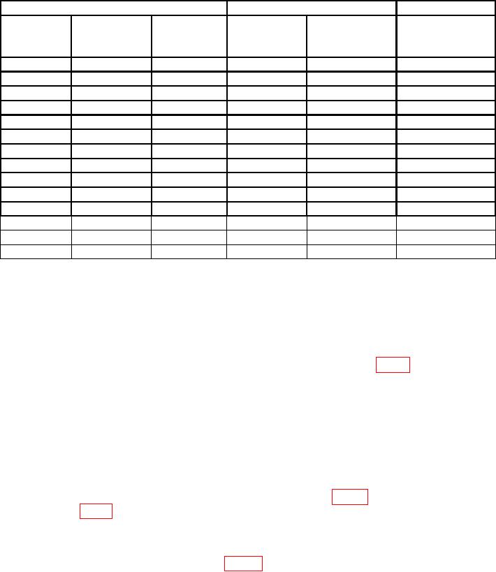
Table 4. Decoder Replies - Continued
Test instrument
Radar test set
Test instrument
Menu 3
Menu 3
ACCEPT/REJEC
FUNC
MODE
CODE
CODES
REPLY
T lamp
SIGNAL
SYSTEM
2
6666
M2: 5555
SIF
REJECT
SYSTEM
2
6666
M2: 6666
SIF
ACCEPT
SYSTEM
2
7777
M2: 6666
SIF
REJECT
SYSTEM
2
7777
M2: 7777
SIF
ACCEPT
EMERG
1
7700
M1: 7700
SIF
REJECT
EMERG
2
7700
M2: 7700
SIF
REJECT
EMERG
3/A
7700
M3/A: 7700
SIF
REJECT
EMERG
C
7700
MC: 7700
SIF
ACCEPT
EMERG
C
7700
MC: 7700
VAR EMERG
REJECT
EMERG
3/A
7700
M3/A: 7700
VAR EMERG
ACCEPT
EMERG
2
7700
M2: 7700
VAR EMERG
ACCEPT
EMERG1
1
7700
M1: 7700
VAR EMERG
ACCEPT
I/P
2
7700
M2: 7700
ID OF POS
ACCEPT
I/P
3/A
7700
M3/A: 7700
ID OF POS
ACCEPT
1Perform
transmitter output power check if emergency mode 1 step produces a flickering ACCEPT light.
b. Adjustments. No adjustments can be made.
14. Read Delay and Error Detector
a. Performance Check
(1) Connect RTS oscilloscope CH 1 probe to test point A10TP6 (fig. 2).
(2) Set FUNCTION switch to SYSTEM, MODE switch to 1, and CODE switches to
7777.
(3) Press PUSH TO TEST switch and turn to LOCK position.
(4) Set RTS menus to INITIAL settings and perform a power measurement. Stop
measurement after reading has been obtained. ACCEPT lamp will glow.
(5) Press RTS oscilloscope AUTO-SCALE pushbutton and set TIME/DIV
switch to 20 s. Verify width of pulse on oscilloscope CH 1 is between 140 and 160 s.
(6) Disconnect CH 1 probe from test point A10TP6 (fig. 2) and connect it to test
point A11TP3 (fig. 2).
(7) Set TIME/DIV switch to .1 SEC. If negative pulse width on CH 1 is not
between 0.34 and 0.36 s, perform b below.
b. Adjustments. Adjust A11R30 (fig. 2) until width of pulse (negative side) on
oscilloscope CH 1 is 0.35 s (R).
15. Reply Evaluator
a. Performance Check
(1) Set MODE switch to 2.