
TB 9-6625-2163-24
Mode 4 Connector Pin Out
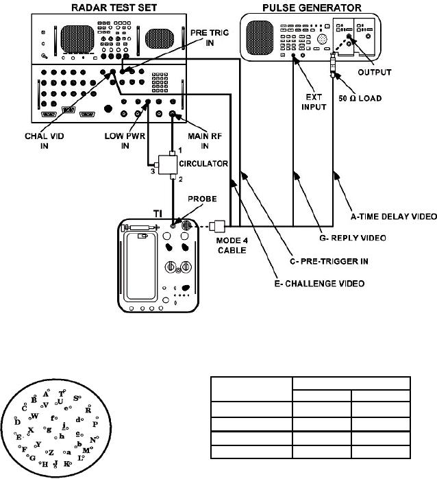
Mode 4 Connector/Cable Pin Out
Mode 4
Mode 4 Connector
Cable
Signal Pin Ground Pin
Time Delay Video
A
B
Pre-Trigger In
C
D
Challenge Video
F
E
Reply Video
G
H
Figure 4. Mode 4 decoder equipment setup.
(4) Set RTS INTERROGATOR MENUS as listed in (a) through (g) below:
(a) Menu 2 M4 to WORD C, all other selections to OFF.
(b) Menu 3 REPLY SIGNAL to MODE 4-3, M1 to MC to OFF, RANGE
DELAY to 3 s, CHAL SOURCE to INTERNAL, F2 to OFF, and SIF2 to OFF.
(c) Menu 8 GATING: to INTERNAL, EXTERNAL: to PASS, INT GATE:
#PASSED: to 64, and #INHIBITED: to 0.
(d) Menu 10 MAIN FREQ to 1090 MHZ.
16