
TB 9-6625-2164-24
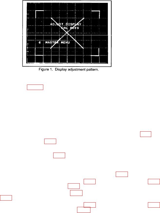
g. Adjust VECT LIN for minimum trace separation of the diagonal lines on the display
pattern as shown in figure 1.
h. Press MEMORY DISPLAY/6 and MENU/TEST pushbuttons. MASTER MENU
will clear display.
i. Press MENU/TEST and MEMORY DISPLAY 4, 5, 6 and MENU/TEST pushbuttons.
j.
Press TRIGGERING/MODE AUTO pushbutton.
k. Press TRIGGERING/COUPLING AC pushbutton.
l.
Press TRIGGERING/SOURCE EXT pushbutton.
m. Connect multimeter positive lead to TP810 and negative lead to TP902 (ground) (fig. 2).
n. Adjust AC ZERO R241 (fig. 3) for 0 V dc 2 mV indication on multimeter.
o. Press TRIGGERING/COUPLING DC pushbutton.
p. Adjust DC BALANCE R240 (fig. 3) for 0 V dc 2 mV indication on multimeter.
q. Press AQR MODE/BOTH pushbutton and position CH 1 and CH 2 POSITION
controls to the center graticule line.
r. Connect shorting cable between TP1220 and TP520 TP GND (fig. 4).
and adjust CH 1 TRIGGER OFFSET R518, (fig. 4) for 0 V 2 mV dc on multimeter.
t. Remove shorting cable from TP1220 (fig. 4) and connect to TP 1230 and TP 520 TP
GND (fig. 4).
and adjust CH 2 TRIGGER OFFSET R445 (fig. 4) for 0 V 2 mV dc indication on