
TB 9-6625-2170-24
(6) Press distortion range 2% and 0.2% pushbuttons in turn and note oscilloscope
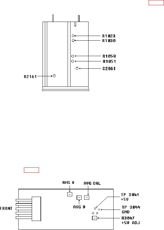
display jump amplitude. If jump amplitude is 100 mV or greater, adjust R1050 (fig. 1) for
minimum jump amplitude, less than 100 mV, when switching between 2% and 0.2% (R).
Figure 1. Test instrument - top view.
(7) Disconnect short and oscilloscope from TI.
(8) Connect calibrator OUTPUT HI and LO to TI INPUT + and -.
(9) Position controls as listed in (a) through (d) below:
(a) FILTERS 80 kHz LO PASS pushbutton released.
(b) FUNCTION LEVEL pushbutton pressed.
(c) FUNCTION VOLTS pushbutton pressed.
(d) RESPONSE RMS/AVG pushbutton pressed to RMS.
(10) Set calibrator for a 15 mV, 1 kHz output.
(11) Adjust RMS 0 (fig. 2) until TI indicates 0.015 V (R).
Figure 2. Test instrument - right view.
7