
TB 9-6625-2170-24
14. Residual THD + N
a. Performance Check
(1) Connect signal generator output to TI INPUT + and -.
(2) Connect TI INPUT - to ground terminal.
(3) Position controls as listed in (a) through (c) below:
(a) INPUT RANGE switch to AUTO RANGE.
(b) Distortion range AUTO RANGE pushbutton pressed.
(c) All FILTERS pushbuttons released.
(4) Position signal generator controls as listed in (a) through (d) below:
(a) FREQUENCY Hz for 100 kHz.
(b) OUTPUT LEVEL(dBm) for 0 dBm.
(c) GNDED/FLTG pushbutton released to FLTG.
(d) OUTPUT ON/OFF pushbuttons pressed to ON.
( 5 ) Press TI FUNCTION THD + N pushbutton. If TI indication is not d 0.015 percent,
perform b below.
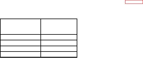
(6) Position signal generator FREQUENCY Hz controls for settings listed in table 8.
If TI does not indicate within limits specified, perform b below.
Table 8. Residual THD + N
Signal generator
FREQUENCY Hz Test instrument
settings
indications
50 kHz
d0.015%
20 Hz1
d0.005%
1 kHz
d0.005%
20 kHz
d0.005%
1Press
FILTERS 80 kHz LO PASS pushbutton.
b. Adjustments
(1) Position controls as listed in (a) through (d) below:
(a) INPUT RANGE switch to 2 V.
(b) Distortion range 0.2 percent pushbutton pressed.
(c) FILTERS 80 kHz LO PASS pushbutton pressed.
(d) All remaining FILTERS pushbuttons released.
LEVEL (dBm) controls for 0 dBm.