
TB 9-6625-2176-35
(b) AMPLITUDE RANGE switch to 50-
500mV.
(7) Repeat (1) through (6) above as
necessary to compensate for interaction of adjustments.
(c) FREQUENCY RANGE switch to
.35-.75.
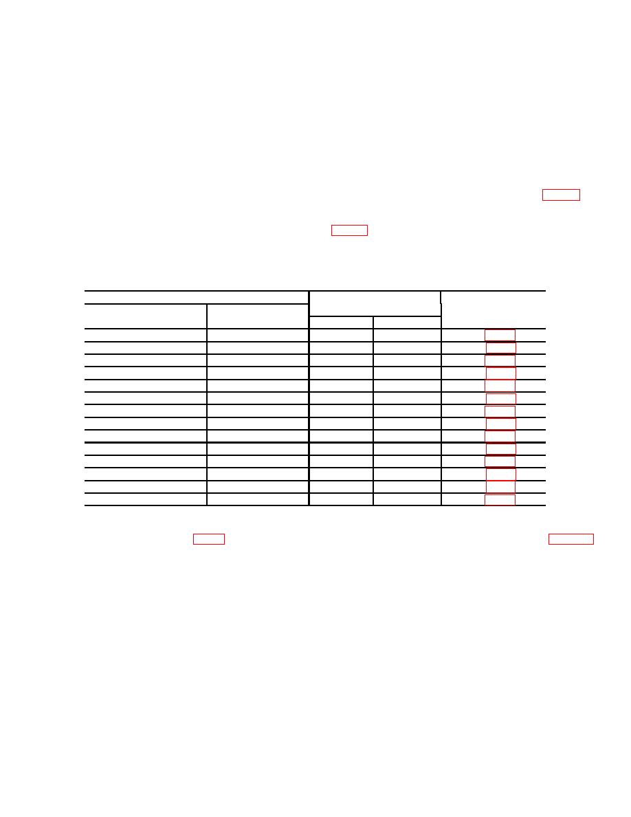
9. Frequency Accuracy.
(d) Frequency dial to .75 on .35.75
scale.
a. Performance Check.
(3) If frequency counter does not indicate
(1) Connect frequency counter (A5) to
between 735 and 765 kHz, perform b below.
OUTPUT, using cable and termination (B3 and B6).
(4) Position TI controls as listed in table 5. If
(2) Position controls as listed in (a) through
frequency counter does not indicate within limits
(d) below:
specified, perform corresponding adjustment listed in
(a) AMPLITUDE switch to 50.
Table 5. Frequency Accuracy
Test instrument
Frequency counter
Adjustments
FREQUENCY RANGE
Frequency dial
indications (MHz)
(R)
switch settings
settings
Min
Max
.35-.75
.35
0.343
0.357
T14 (fig.
.75-1.6
1.6
1.568
1.632
C18 (fig.
.75-1.6
.75
0.735
0.765
T18 (fig.
1.6-3.6
3.6
3.528
3.672
C22 (fig.
1.6-3.6
1.6
1.568
1.632
T22 (fig.
3.6-8
8
7.840
8.160
C26 (fig.
3.6-8
3.6
3.528
3.672
T26 (fig.
8-18
18
17.640
18.360
C30 (fig.
8-18
8
7.840
8.160
T30 (fig.
18-42
42
41.160
42.840
C34 (fig.
18-42
18
17.640
18.360
T34 (fig.
42-100
100
98.00
102.00
C38 (fig.
42-100
42
41.160
42.840
T38 (fig.
50 kHz ONLY
.5
0.049
0.051
T10 (fig.
(1) Connect equipment as shown in figure 3,
counter indication of 750 kHz (R).
connection A.
(2) Position controls as listed in (a) through
10. Frequency Response
(c) below:
a. Performance Check
Change 1
7
