
TB 9-6625-2224-24
14. Power Supply
a. Performance Check
NOTE
Do not perform power supply checks if all other parameters are
within tolerance.
NOTE
C205 may either be chassis mounted or located on HIGH
VOLTAGE (A100) board.
(1) Connect multimeter negative to positive side of C205 (fig. 2) (white-violet wire),
and multimeter positive to negative side of C205 (fig. 2) (violet wire). If multimeter does
not indicate between -348 and -352 V dc (-398 and -402 V dc), perform b (l) below.
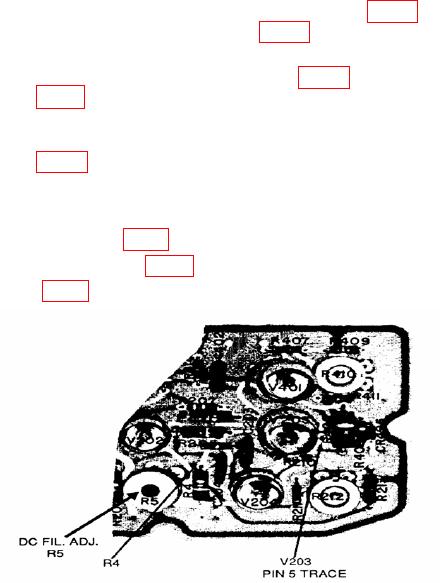
(2) Connect multimeter negative to top of R4 (fig. 3) and multimeter positive to
V203 PIN 5 TRACE (fig. 3). If multimeter does not indicate between -6.05 and -6.25 V dc,
perform b (2) below.
(3) Connect multimeter negative to chassis ground and multimeter positive to
positive side of C53 (fig. 3). If multimeter does not indicate between +19 and +21 V dc,
perform b (3) below.
b. Adjustments
(1) Adjust HV ADJ. R212 (fig. 2) for a -350 V dc (400 V dc) indication on multimeter (R).
(2) Adjust DC FIL. ADJ. R5 (fig. 3) for a -6.15 V dc indication on multimeter (R).
(3) Adjust R53 (fig. 2) for a +20 V dc indication on multimeter (R).
Figure 3. High voltage board (A100) - partial view.
15. Final Procedure
a. Deenergize and disconnect all equipment.
b. Annotate and affix DA label/form in accordance with TB 750-25.
13/(14 Blank)