
TB 9-6625-2224-24
9. Attenuator Accuracy SG-644/U (Hewlett-Packard, Model 8614A)
a. Performance Check
NOTE
Settings and indications in parenthesis are for SN prefixed 501
and above.
(1) Position controls as listed in (a) through (d) below:
RF pushbutton released to out position.
(a)
INTERNAL ALC pushbutton released to out position.
(b)
FREQUENCY (MC) control to 0800.
(c)
ATTENUATION (DB) control to 000.
(d)
NOTE
Verify that the proper CAL FACTORS are loaded for the
measuring receiver power sensor module.
(2) Zero and calibrate the measuring receiver power sensor module.
(3) Set up measuring receiver to measure tuned level RF power in dB.
(4) Connect measuring receiver power sensor module to RF POWER OUTPUTS CAL.
(5) Press RF pushbutton and establish a 0 dB reference on the measuring receiver
at 800 MHz.
(6) Adjust ATTENUATION (DB) control to each setting in table 4. Measuring
receiver will indicate within limits specified.
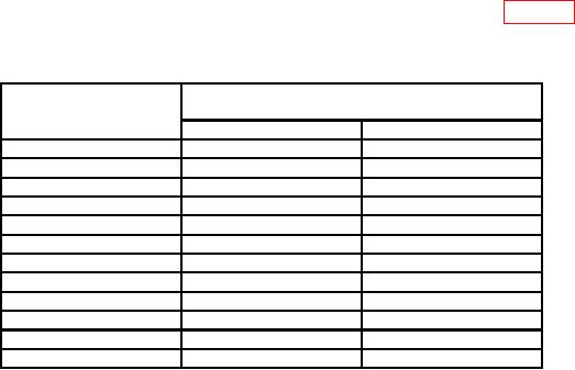
Table 4. Attenuator Accuracy
Test instrument
Measuring receiver indications
ATTENUATION (DB)
(dB)
dial indications
Min
Max
010 (015)
10.0
(15.0)
13.0
(18.0)
020 (025)
19.68
(24.68)
20.32
(25.32)
030 (035)
29.62
(34.62)
30.38
(35.38)
040 (045)
39.56
(44.56)
40.44
(45.44)
050 (055)
49.50
(54.50)
50.50
(55.50)
060 (065)
59.44
(64.44)
60.56
(65.56)
070 (075)
69.38
(74.38)
70.62
(75.62)
080 (085)
79.32
(84.32)
80.68
(85.68)
090 (095)
89.26
(94.26)
90.74
(95.74)
100 (105)
99.20 (104.20)
100.80 (105.80)
110 (115)
109.14 (114.14)
110.86 (115.86)
120 (125)
119.08 (124.08)
120.92 (125.92)
b. Adjustments. No adjustments can be made.