• Home
  • Download PDF
  • Order CD-ROM
  • Order in Print
Table 3. Frequency and Stability
Figure 2. Test instrument top view.

Calibration Procedure For Signal Generator, Sg-644/U (Model 8614A) And 8616A Page Navigation
  2    3    4    5    6  7  8    9    10    11    12  
img
. . .
TB 9-6625-2224-24
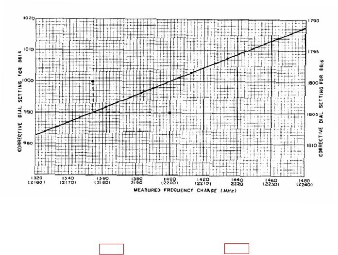
EXAMPLE: If difference is 1354 MHz, the corrective dial setting in 990 MHz.
Figure 1. Frequency dial correction chart.
(4) Adjust FREQUENCY (MC) control to 1000 (1800).  Loosen the two DIAL
PLUNGER SET SCREWS (fig. 2), hold the DIAL PLUNGER (fig. 2) stationary, and set dial
to correction value determined in b (3) above. Tighten DIAL PLUNGER SET SCREWS (R).
(5) Repeat b (l) through (4) above as necessary.
7


Privacy Statement
Press Release
Contact

© Copyright Integrated Publishing, Inc.. All Rights Reserved.