
TB 9-6625-2240-24
b. Adjustments
(1) Set oscilloscope calibrator VOLTAGE output as listed in table 21.
(2) Adjust TI VOLTS/DIV controls for 6 divisions of vertical deflection on TI.
(3) Disconnect oscilloscope calibrator from TI and connect TI CALIBRATOR
(front panel) and (ground) (front panel) to TI CH1 input.
(4) Adjust R1515 (fig. 3) for 6 divisions of vertical deflection on TI (R).
13. Power Supply
NOTE
Do not perform power supply checks if all other parameters are
within tolerance.
a. Performance Check
(1) Connect multimeter to TI test point +50 V (fig. 3) and chassis ground.
Multimeter will indicate as listed in table 22 below; if not, perform b below.
(2) Repeat technique of (1) above for TI test points and voltage indications listed in
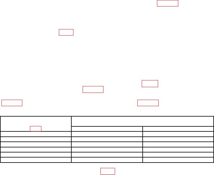
Table 22. Power Supply Voltage
Test instrument
Multimeter indications
test points
(V dc)
Min
Max
+50
V
+49.75
+50.25
+110
V
+107
+113
+15
V
+14.77
+15.23
+5
V
+4.92
+5.08
-15
V
-14.77
-15.23
-8
V
-7.88
-8.12
b. Adjustments. Adjust R1430 +50 V (fig. 3) for multimeter indication of +50 V (R).
14. Final Procedure
a. Deenergize and disconnect all equipment and reinstall protective cover on TI.
b. Annotate and affix DA label/form in accordance with TB 750-25.