
TB 9-6625-2240-24
(c) Rotate oscilloscope calibrator knob located below EDIT FIELD pushbutton
to adjust amplitude for 5 divisions on TI crt and measure risetime using standard risetime
technique. Risetime limits are listed in table 18.
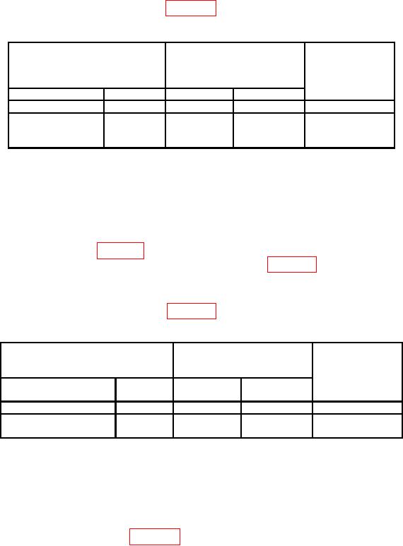
Table 18. Channel 1 Risetime Measurement
Test instrument
Oscilloscope calibrator
Test instrument
risetime
EDGE
switch settings
limits
output settings
(≤)
VOLTS/DIV
TIME/DIV
Amplitude
0.01 s
5m
25 mVpp
10 MHz
1.75 ns
0.01 s
10 m
50 mVpp
10 MHz
1.4 ns
(Tektronix,
Type 475A)
(26) Move connection on TI to CH2 and press VERT MODE CH2 pushbutton (in).
NOTE
Ensure CH2 VOLTS/DIV AC GND DC switch is set to DC for
steps below.
(27) Set TI VOLTS/DIV, TIME/DIV settings and oscilloscope calibrator EDGE
output to settings listed in table 19. Use technique of step (28) below for TI switch settings
and oscilloscope calibrator EDGE output settings listed in table 19.
(28) Rotate oscilloscope calibrator knob located below EDIT FIELD pushbutton to
adjust amplitude for 5 divisions on TI crt and measure risetime using standard risetime
technique. Risetime limits are listed in table 19.
Table 19. Channel 2 Risetime Measurement
Oscilloscope calibrator
Test instrument
EDGE
Test instrument
switch settings
output settings
risetime
limits
TIME/DI
Amplitude
VOLTS/DIV
(≤)
V
0.01 s
5m
25 mV pp
10 MHz
1.75 ns
0.01 s
10 m
50 mV pp
10 MHz
1.4 ns
(Tektronix, Type 475A)
(29) Press VERT MODE CH1 pushbutton (in), and set X10 MAG pushbutton (out).
(30) Connect CH1 through 50 Ω feedthrough termination to oscilloscope calibrator
CHAN 1.
(31) Press oscilloscope calibrator LEVEL SINE pushbutton to illuminate green LED.
(32) Set TI VOLTS/DIV, TIME/DIV settings and oscilloscope calibrator LEVEL
SINE output to settings listed in table 20.
(33) Rotate oscilloscope calibrator knob below EDIT FIELD pushbutton to adjust
amplitude for 6 divisions of vertical deflection on TI.
18