
TB 9-6625-2250-24
19. Frequency Drift
a. Performance Check
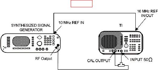
(1) Connect equipment as shown in figure 7.
Figure 7. Frequency drift - equipment setup.
(2) Set synthesized signal generator frequency to 300.0015 MHz and level
to -15 dBm. Press synthesized signal generator OUTPUT On Off pushbutton to Off.
(3) Press TI keys and enter values using DATA keys as listed in (a) through (f) below:
INSTRUMENT STATE PRESET.
(a)
FREQUENCY then [CENTER FREQ] to 300 MHz.
(b)
SPAN then [SPAN WIDTH] to 2.5 kHz.
(c)
CONTROL BW then [RES BW] to 100 Hz.
(d)
AMPLITUDE then [REF LVL] to 8 dBm.
(e)
LOG dB/DIV to 2 dB.
(f)
(4) Press TI keys as listed in (a) through (d) below:
MARKER PEAK SEARCH.
(a)
[MARKER
CF] wait for completion of sweep.
(b)
FREQUENCY.
(c)
STEP three times.
(d)
(5) Verify signal is about 2 divisions from leftmost graticule line.
(6) Press synthesized signal generator OUTPUT On Off pushbutton to On.
(7) Press TI keys as listed in (a) through (e) below:
CONTROL TRIG.
(a)
[SINGLE] wait for completion of sweep.
(b)
MARKER PEAK SEARCH.
(c)
[MARKER DELTA].
(d)
[NEXT PEAK].
(e)
38