
TB 9-6625-2250-24
(h) [MORE].
(i) [REF LVL CAL].
(3) Slowly adjust TI knob until MKR amplitude indication is between -9.83 and
-10.17 dBm.
(4) Press [STORE REF LVL] key.
NOTE
Set the measuring receiver to measure power. Zero and
calibrate measuring receiver sensor module.
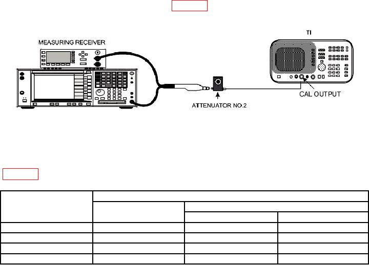
(5) Connect equipment as shown in figure 8.
Figure 8. Marker amplitude accuracy test - equipment setup.
(6) Set attenuator No. 2 to 0 dB.
(7) Setup measuring receiver to measure power in dBm at 300 MHz. Record
measuring receiver indication as ideal MKR indication for TI [REF LVL] 0 dBm setting in
Table 17. Marker Amplitude Accuracy
Attenuator
Test instrument
[REF LVL] settings
MKR indications
No. 2 settings
(dB)
(dBm)
Ideal
Actual
0
0
60
-10
60
-40
60
-50
(8) Disconnect sensor module from attenuator No. 2 and connect open end of
attenuator No. 2 to TI INPUT 50 .
(9) Press TI keys to values using DATA keys as listed in (a) through (f) below:
INSTRUMENT STATE PRESET.
(a)
FREQUENCY then [CENTER FREQ] to 300 MHz.
(b)
SPAN then [ZERO SPAN].
(c)
CONTROL BW then [RES BW] to 300 kHz.
(d)
40