
TB 9-6625-2251-24
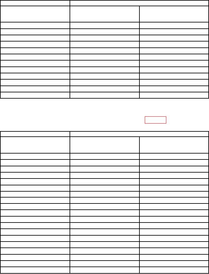
Table 14. MODE A Horizontal Linearity Accuracy - Continued
Oscilloscope calibrator
Test instrument
A and B
Display
MARKER
SEC/DIV
Tolerance
setting
output
(major divisions)
s/div
0.1
0.1
ms/div
100
s/div
0.1
0.2
ms/div
200
s/div
0.1
0.5
ms/div
500
0.1
1
ms/div
1
ms/div
0.1
2
ms/div
2
ms/div
0.1
5
ms/div
5
ms/div
0.1
10
ms/div
10
ms/div
0.1
20
ms/div
20
ms/div
0.1
50
ms/div
50
ms/div
0.1
s/div1
0.1
100
ms/div
0.1
0.2
s/div
200
ms/div
0.1
0.5
s/div
500
ms/div
1Select
TRIGGER MODE and set NORMAL to on.
g. Select HORIZONTAL MODE B and set TRIGGER MODE to AUTO.
h. Use technique of b through f above for settings listed in table 15.
Table 15. MODE B Horizontal Linearity Accuracy
Oscilloscope calibrator
Test instrument
A AND B
Display
MARKER
SEC/DIV
tolerance
output
setting
(major divisions)
s/div
0.1
500
ns/div
0.5
s/div
s/div
0.1
1
1
s/div
s/div
0.1
2
2
s/div
s/div
0.1
5
5
s/div
s/div
0.1
10
10
s/div
s/div
0.1
20
20
s/div
s/div
0.1
50
50
s/div
0.1
0.1
ms/div
100
s/div
0.1
0.2
ms/div
200
s/div
0.1
0.5
ms/div
500
0.1
1
ms/div
1
ms/div
0.1
2
ms/div
2
ms/div
0.1
5
ms/div
5
ms/div
0.1
10
ms/div
10
ms/div
0.1
20
ms/div
20
ms/div
0.1
50
ms/div
50
ms/div
0.1
s/div1
0.1
100
ms/div
0.1
0.2
s/div
200
ms/div
0.1
0.5
s/div
500
ms/div
1Select
TRIGGER MODE and set NORMAL to on
12