TB 9-6625-2274-40
b. Press CONTINUE pushbutton to display 5 V * 1 X 1. Multimeter will indicate
between 4.9963 and 5.0038 V dc. If multimeter does not indicate within limits specified,
adjust VAR dial until multimeter indicates within limits specified and as close to the
nominal value as possible.
c. Press CONTINUE pushbutton and repeat technique of b above for settings listed in
table 6. Multimeter will indicate within limits specified.
d. When display indicates CAL DONE, set cal/normal switch A9S1061 (fig. 1) to the
normal position (up).
e. Remove multimeter connections.
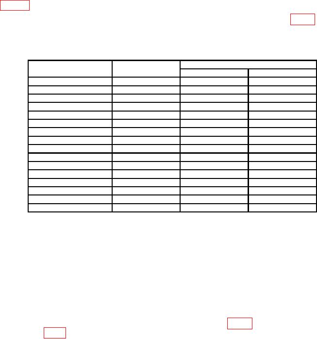
Table 6. Calibration Factor Adjustments
Test instrument
Multimeter indications
indications
Nominal value
Min
Max
50 mV * 2 X 1
50.000
mV
49.963
mV dc
50.038
mV dc
50 mV * 3 X 1
50.000
mV
49.963
mV dc
50.038
mV dc
0.1 V * 4 X 1
-100.000
mV
-99.925
mV dc -100.075
mV dc
5 V *5X1
-5.0000 V
-4.9963 V dc
-5.0038
V dc
1 V *6X1
-1.0000 V
-0.99925 V dc
-1.00075
V dc
1 V *7X1
1.0000 V
0.99925 V dc
1.00075
V dc
10 mA * 8 X 10
5.0000 V
4.9963 V dc
5.0038
V dc
50 mV * 9 X 11
50.000
mV
49.963
mV dc
50.0038
mV dc
50 mV * 10 X1
50.000
mV
49.963
mV dc
50.0038
mV dc
10 V * 11 X1
-10.000
V
-9.9925 V dc
-10.0075
V dc
10 V * 12 X10
-100.000
V
-99.925
V dc
-100.075
V dc
0.1 V
* 13 X1
-100.000
mV
-99.925
mV dc
100.075
mV dc
2 V * 14 X6
-12.000
V
-11.991
V dc
-12.009
V dc
2 V * 15 X1
-5.000
V
-4.9963 V dc
-5.0038
V dc
50 V
* 16 X2
-100.000
V
-99.925
V dc
-100.075
V dc
CAL DONE
1Remove
50
feedthrough termination.
19. Offset
a. Position controls as listed in (1) through (4) below:
(1) Press AMPLITUDE MODE AMPL MODE VOLT pushbutton.
pushbutton to highlight + DC.
(2) Press AMPLITUDE MODE FREQ
pushbutton display
(3) Press AMPLITUDE MODE NUMBER OF DIV
X 1 DIV.
(4) Adjust UNITS/DIV dial to display 10 V/D.
b. Connect multimeter positive lead to A6TP1200 (fig. 1) and negative lead to
A6TP1202 (fig. 1).
c. Adjust A6R1532 (fig. l) for a multimeter indication of 10.0000 V dc 0.0010 V (R).
d. Remove multimeter connections. Connect multimeter to OUTPUT.
e. Adjust UNITS/DIV dial to display .1 V/D.

