
TB 9-6625-2280-35
10. Power Linearity Test
a. Performance Check
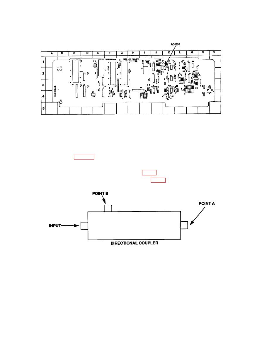
(1) Refer to figure 2 and connect equipment as listed in (a) through (c) below:
(a) Connect signal generator RF OUTPUT to directional coupler INPUT.
(b) Connect power meter to POINT A (fig. 2) of directional coupler.
(c) Connect 50 Ω termination to POINT B (fig. 2) of directional coupler.
NOTE
Ensure power meter zero is maintained throughout this
performance check by setting signal generator RF OFF/ON
key to the OFF position and checking power meter zero
indication.
