
TB 9-6625-2281-24
(3) Adjust signal generator output in 10 dBm steps to -70 dBm.
Allow the
measuring receiver to acquire the signal at each level.
(4) Adjust signal generator output for 0.0 dBm indication on measuring receiver.
(5) Configure measuring receiver in the ratio mode.
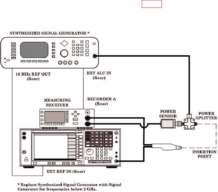
(6) Connect TI at TI INSERTION POINT as shown in figure 1.
(7) Measure insertion loss of TI at test frequencies determined in 7 c above.
Measuring receiver will indicate within the limits listed in appendixes A, B, or C.
Figure 1. Equipment Setup.
9. Final Procedure
a. Deenergize and disconnect all equipment.
b. Annotate and affix DA label/form in accordance with TB 750-25.
5/(6 blank)