
TB 9-6625-2303-35
(3) Connect other end of BNC T connector to frequency counter.
(4) Adjust audio analyzer frequency controls for a frequency counter indication 1000 Hz.
(5) Disconnect frequency counter from BNC T connector.
(6) Connect end of BNC T connector to multimeter (ac mode).
(7) Set factor switch to 1.
(8) Adjust audio analyzer amplitude output controls for a digital multimeter
indication between 0.1591 V rms, 0.00005 V rms.
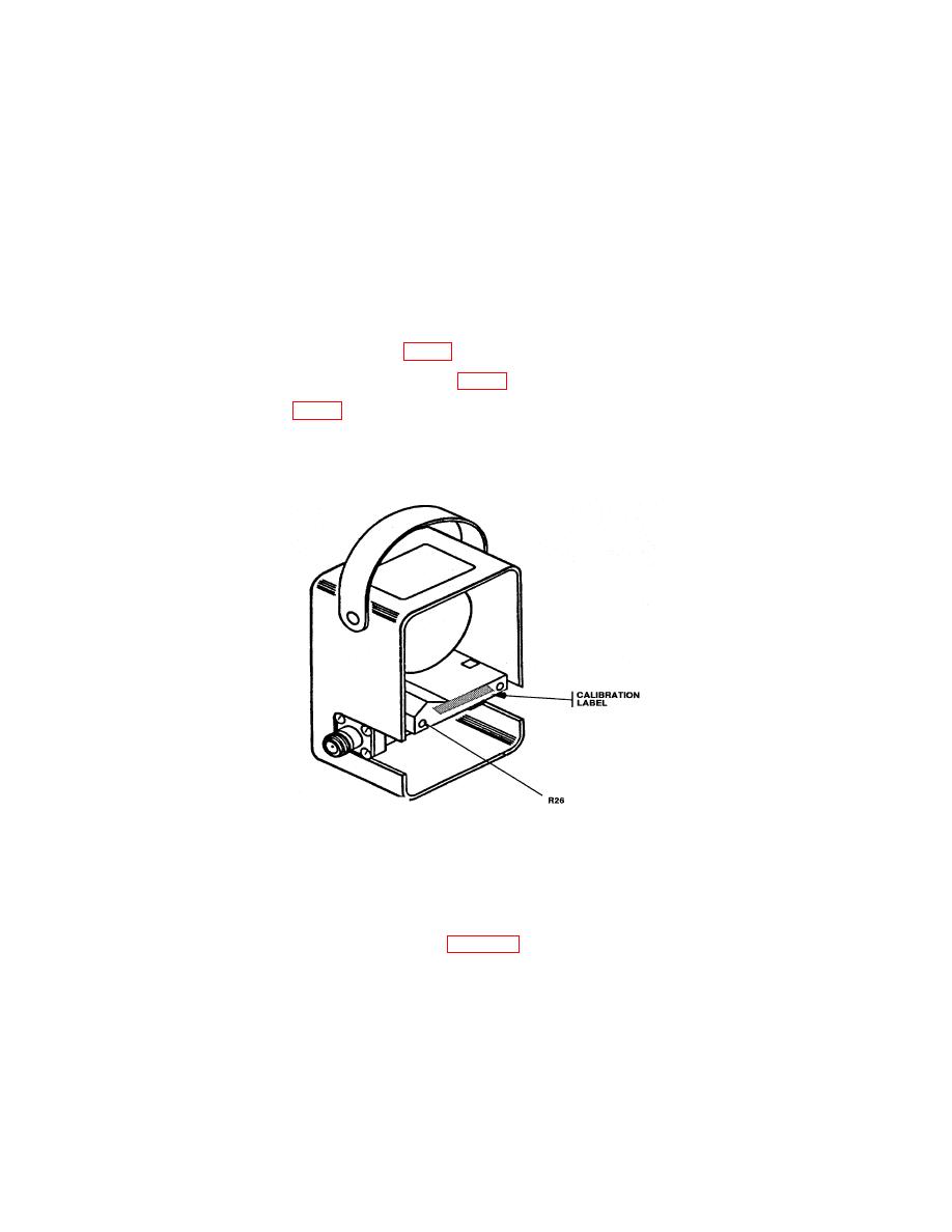
(9) Locate access hole to R26 (fig. 1).
(10) Pierce paper strip covering R26 (fig. 1) adjustment.
(11) Adjust R26 (fig. 1) until meter pointer rests on 1 on the uppermost scale.
(12) Replace back cover and four screws removed in b (l) above.
(13) Remove calibration element from TI.
a. Performance Check
(1) Connect equipment as shown in figure 2.
(2) Insert plug-in element into wattmeter and rotate it until the arrow points in the
direction of 50 Ω termination.
(3) Set factor switch to 1 position and allow equipment to warm-up for 5 minutes.
of 1000 MHz.
