
TB 9-6625-2309-24
Shift magnitude will typically be 0.5 meter for first cluster (all
optical modules); 2 meters for TD-260C, 4 meters for TD-261C,
and 8 meters for TD-285C for second cluster.
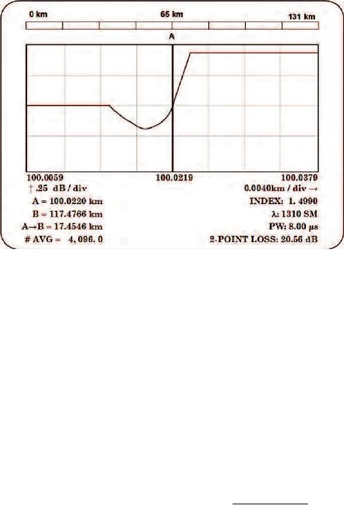
Figure 6. Example of cursor placement if undershoot is present (TD-285C).
(13) Repeat technique of steps a (3), (4) (b), (11) and (12) for next digital delay/pulse
generator A=T+ value on TD-260C data sheet (appendix A) (first cluster) until a shift to
right of cursor A FOCUS generated pulse is observed. Record this A= km TI indication on
data sheet. When shift occurs, this is the final measurement required for this cluster.
NOTE
Press TI PULSE WIDTH pushbutton to select LONG for
second cluster measurements.
(14) Repeat technique of steps a (1) through (13) for second cluster using A=T+
values on TD-260C data sheet (second cluster).
(15) Load TS-4320 Optical Fiber Test Set calibration software to an MS-DOS
compatible PC according to instructions in TS-4320, Calibration Software User's Manual.
(16) Access Distance Scale Calibration menu.
(17) Access data entry page and enter insertion delay and index of refraction (1.
4990) for constants entry. On data edit page enter only last two digital delay/pulse
generator settings for A=T+ ( s) and respective TI A= (km) values for each cluster from
TD-260C data sheet (appendix A).
13