
TB 9-6625-2323-24
7. Equipment Setup
WARNING
HIGH VOLTAGE is used or exposed during the performance of
this calibration.
DEATH ON CONTACT may result if
personnel fail to observe safety precautions.
REDUCE
OUTPUT(s) to minimum after each step within the
performance check where applicable.
a. Remove TI protective cover only as necessary to make adjustments.
CAUTION
Before connecting TI to power source, make sure TI is set to the
power source line voltage as shown on rear of TI.
b. Connect TI to 115 V ac power source.
c. Press LINE switch to OPERATE and allow at least one hour for TI to warm-up and stabilize.
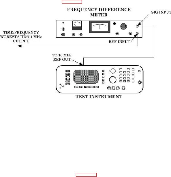
d. Connect equipment as shown in figure 1.
Figure 1. Time base verification hook-up.
NOTE
TI must have power applied and in STANDBY or OPERATE
for at least 120 continuous hours before the frequency drift
specification can be verified.
f. Disconnect frequency difference meter from the TI and the time/frequency workstation.
8. Frequency Accuracy
a. Performance Check
(1) Connect equipment as indicated in figure 2.