
TB 9-6625-2323-24
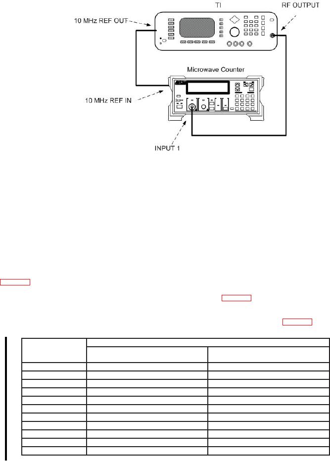
Figure 2. Frequency resolution accuracy hook-up.
(2) Press TI keys as listed in (a) through (e) below.
(a) System, Reset.
(b) Output On Off to off.
(c) Level Control, L0, Edit L0, 0, and MHz ms dB.
(d) Frequency Control, F0, Edit F0, 1, and GHz Sec dBm.
(e) Output On Off to on.
(3) Set microwave frequency counter to measure frequency on INPUT 1.
(4) Verify that the microwave frequency counter indicates within limits listed in
(5) Set TI frequency to the next frequency listed in table 3, using the TI arrow pad,
and repeat (4) above.
(6) Repeat (4) and (5) above for the remaining frequencies listed in table 3.
Table 3. Frequency Resolution Accuracy
Test instrument
Microwave frequency counter indications
center frequency
Min (Hz)1
Max (Hz)1
(GHz)
1.000000000
999999900
(999999990)
1000000100
(1000000010)
1.000000100
1000000000
(1000000090)
1000000200
(1000000110)
1.000000200
1000000100
(1000000190)
1000000300
(1000000210)
1.000000300
1000000200
(1000000290)
1000000400
(1000000310)
1.000000400
1000000300
(1000000390)
1000000500
(1000000410)
1.000000500
1000000400
(1000000490)
1000000600
(1000000510)
1.000000600
1000000500
(1000000590)
1000000700
(1000000610)
1.000000700
1000000600
(1000000690)
1000000800
(1000000710)
1.000000800
1000000700
(1000000790)
1000000900
(1000000810)
1.000000900
1000000800
(1000000890)
1000001000
(1000000910)
1.000001000
1000000900
(1000000990)
1000001100
(1000001010)
See footnote at end of table.
6 Change 1