
TB 9-6625-2323-24
Table 13. External AM Frequency Response
Measuring receiver
indication
Audio analyzer
output frequency
Min
Max
Test description
(Hz)
(dB)
(dB)
100
Hz
Response
100
-0.3
0.3
1
kHz
Response
1000
-0.3
0.3
2
kHz
Response
2000
-0.3
0.3
5
kHz
Response
5000
-0.3
0.3
10
kHz
Response
10000
-0.3
0.3
(15) Reduce all outputs to minimum.
(16) Disconnect equipment setup.
b. Adjustments. No further adjustments can be made.
13. Frequency Modulation
a. Performance Check
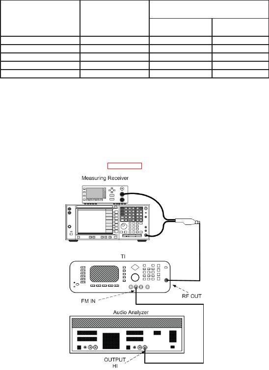
(1) Connect equipment as shown in figure 5.
Figure 5. Frequency modulation hook-up.
(2) Set measuring receiver to measure frequency modulation, with +PEAK detector,
<20 Hz high pass and >200 kHz lo pass filters.
(3) Press TI keys as listed in (a) through (j) below.
(a) System, Reset.
(b) Output On Off to off.
(c) Level Control, L1, Edit L1, 0, and MHz ms dB.