
TB 9-6625-2337-24
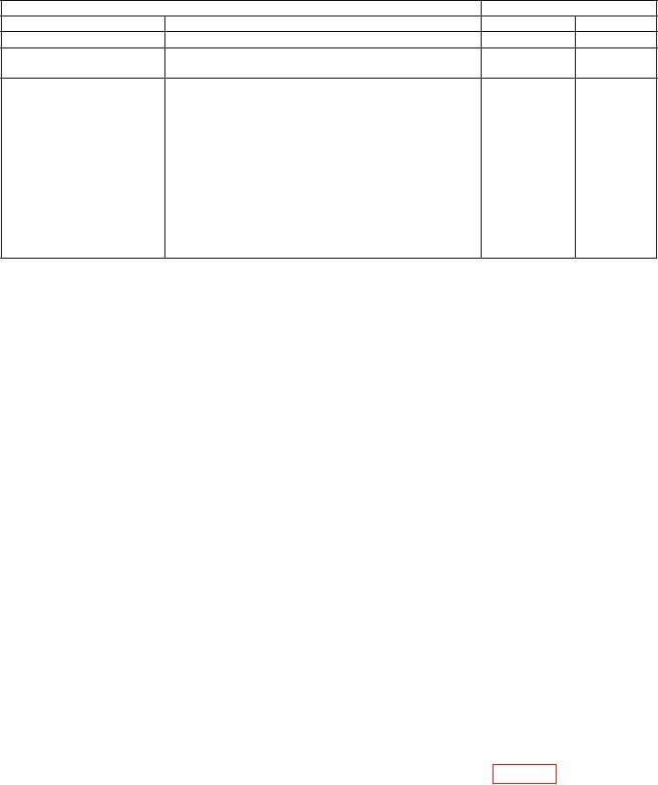
Table 23. Range Delay
TI
Oscilloscope
Test description
Settings
Minimum
Maximum
RANGE DLY 3 s
2.5 s
3.5 s
---------------------------------------
RNG DLY 4096 s
Use the arrow keys to highlight RANGE DELAY:
4.0982 ms
4.0998 ms
4096, ENTR, (4096 s)
2
371.5 s
372.5 s
Press FUNC,
1
RANGE DLY M4
, ENTR (CHALLENGES)
Use the arrow keys to highlight M1:
ENTR (OFF)
Use the arrow keys to highlight M4:
ENTR (WORD A)
3 ress FUNC,
P
, ENTR (1ST REPLY)
Use the arrow keys to highlight REPLY SIGNAL:
ENTR (MODE 4-3)
Use the arrow keys to highlight RANGE DELAY:
0, ENTR, (0 s)
1Disconnect IFF VIDEO CHAL/TAG from oscilloscope. Connect the TRIGGER M4 PRE OUT output to
channel 1 of the oscilloscope using a 93 feedthrough termination.
(38) Reduce all outputs to minimum and disconnect equipment setup.
b. Adjustments. No adjustments can be made.
13. Second Reply
a. Performance Check
(1) Connect the IFF VIDEO SECOND REPLY to channel 1 of the oscilloscope
using a 75 feedthrough termination.
(2) Press TI keys as listed in (a) through (m) below:
Press FUNC, ENTR keys.
(a)
Use the arrow keys to highlight GENERAL MENUS and press ENTR key.
(b)
4, ENTR (2ND REPLY).
(c)
Use the arrow keys to highlight SIF CODE:.
(d)
0000, ENTR.
(e)
Use the arrow keys to highlight F2:.
(f)
ENTR, (OFF).
(g)
Press FUNC, .
(h)
3, ENTR (1ST REPLY).
(i)
Use the arrow keys to highlight REPLY SIGNAL:.
(j)
ENTR (SIF).
(k)
Use the arrow keys to highlight M2:2222.
(l)
ENTR (ON).
(m)
(3) Set oscilloscope to trigger on channel 1 and channel 1 measurement type to
rise time.
(4) Oscilloscope will indicate within limits listed in first row of table 24.