
TB 9-6625-2342-24
y. Repeat technique of d through s above for oscilloscope calibrator outputs and TI
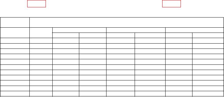
Table 4. Vertical Gain and Volts Cursor Accuracy CH 2
Oscilloscope
Test instrument
calibrator
VOLTS/
Output
Cursor limits
+ Peak limits
Peak limits
DIV
Min
Max
Min
Max
Min
Max
1.2 mV
10 mV
2 mV
9.72 mV
10.28 mV
8.5 mV
11.5 mV
1.2 mV
2.2 mV
20 mV
5 mV
19.40 mV
20.60 mV
17.2 mV
22.8 mV
2.2 mV
4.0 mV
50 mV
10 mV
48.60 mV
51.40 mV
44.4 mV
55.6 mV
4.0 mV
7.2 mV
.1 V
20 mV
97.20 mV
102.80 mV
89.6 mV
110.4 mV
7.2 mV
16.0 mV
.2 V
50 mV
194.0 mV
206.0 mV
178.0 mV
222.0 mV
16.0 mV
36.0 mV
.5 V
.1 V
486.0 mV
514.0 mV
448.0 mV
552.0 mV
36.0 mV
72.0 mV
1
V
.2 V
972
mV
1.03 V
896 mV
1.10 V
72.0 mV
160
2
V
.5 V
1.94 V
2.06 V
1.8 V
2.2
V
160 mV
mV
360
5
V
1 V
4.86 V
5.14 V
4.5 V
5.5
V
360 mV
mV
710
10
V
2 V
9.72 V
10.28 V
9.0 V
11.0
V
710 mV
mV
1.6
20
V
5 V
19.4
V
20.6 V
17.8 V
22.2
V
1.6 V
V
z. Set oscilloscope calibrator output to minimum.
aa. Rotate CH 2 VOLTS/DIV control to set CH 2 for a 1 V indication on CRT.
ab. Rotate CURSOR/DELAY control to position active cursor 3 divisions above CRT
horizontal centerline.
ac. Select CURSOR SELECT and rotate CURSOR/DELAY control to position active
cursor 3 divisions below CRT horizontal centerline. CURSOR VOLTS readout will
indicate between 5.94 V and 6.06 V.
10. Bandwidth Accuracy
NOTE
If TI does not perform as specified, perform adjustments as
indicated in SECTION IV.
a. Press PRGM button then press RECALL button in main menu.
b. Use arrow labeled switches to underline FPNL.
c. Press RECALL button.
d. Select VERTICAL MODE and set CH 2 to off.
e. Rotate CH 1 VOLTS/DIV knob to set CH 1 for a 5 mV indication on CRT. Adjust
HORIZONTAL A AND B SEC/DIV controls for 5 s indications on CRT.
f. Set oscilloscope calibrator output for CHAN 1, LEVEL SINE output frequency of 50
kHz and amplitude for 6 divisions peak-to-peak signal on TI CRT. Adjust TRIGGER
LEVEL control as necessary to obtain a stable display.