
TB 9-6625-2347-35
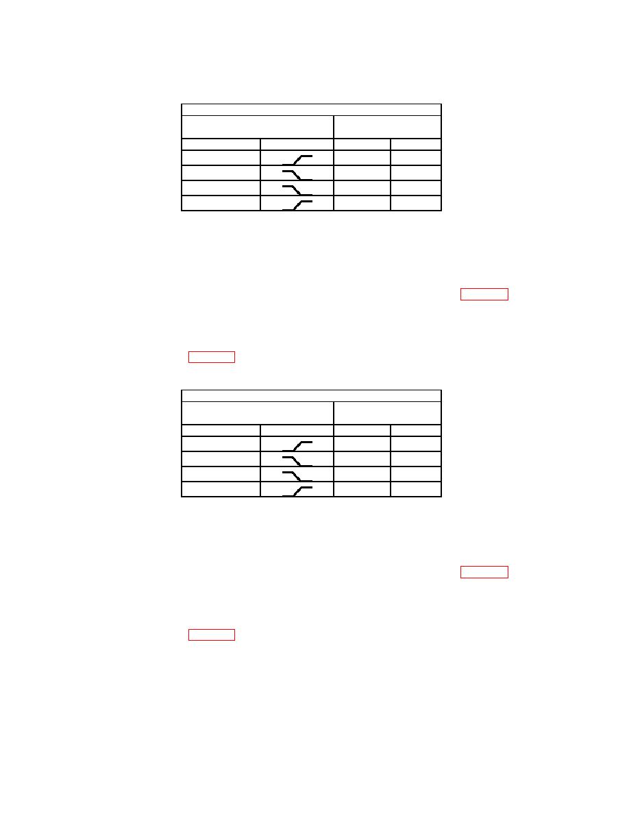
Test instrument
TRIGGER switch
TRIGGER LEVEL
stable display
MODE
SLOPE
YES
NO
AUTO
AUTO
NORM
NORM
(8) Set TI VERTICAL MODE CH1 BOTH CH2 switch to CH 2.
(9) Set oscilloscope calibrator to STANDBY and move connection to TI CH 2 OR Y
input.
(10) Set oscilloscope calibrator to OPERATE.
(11) Set TI TRIGGER switches to combination listed in first row of table 13.
(12) Adjust TI TRIGGER LEVEL control to obtain a stable display. If a stable
display cannot be obtained perform b below.
(13) Repeat technique of (11) and (12) above for remaining TRIGGER pushbutton
combinations listed in table 13. If a stable display cannot be obtained perform b below.
Test instrument
TRIGGER switch
TRIGGER LEVEL
stable display
MODE
SLOPE
YES
NO
NORM
NORM
AUTO
AUTO
(14) Set TI SEC/DIV switch to .05 s.
(15) Set oscilloscope calibrator for a CHAN 1, LEVEL SINE output of 60 MHz and
1.5 divisions of vertical display on TI.
(16) Set TI TRIGGER switches to combination listed in first row of table 14.
(17) Adjust TI TRIGGER LEVEL control to obtain a stable display. If a stable
display cannot be obtained perform b below.
(18) Repeat technique of (16) and (17) above for remaining TRIGGER pushbutton
combinations listed in table 14. If a stable display cannot be obtained perform b below.
20
