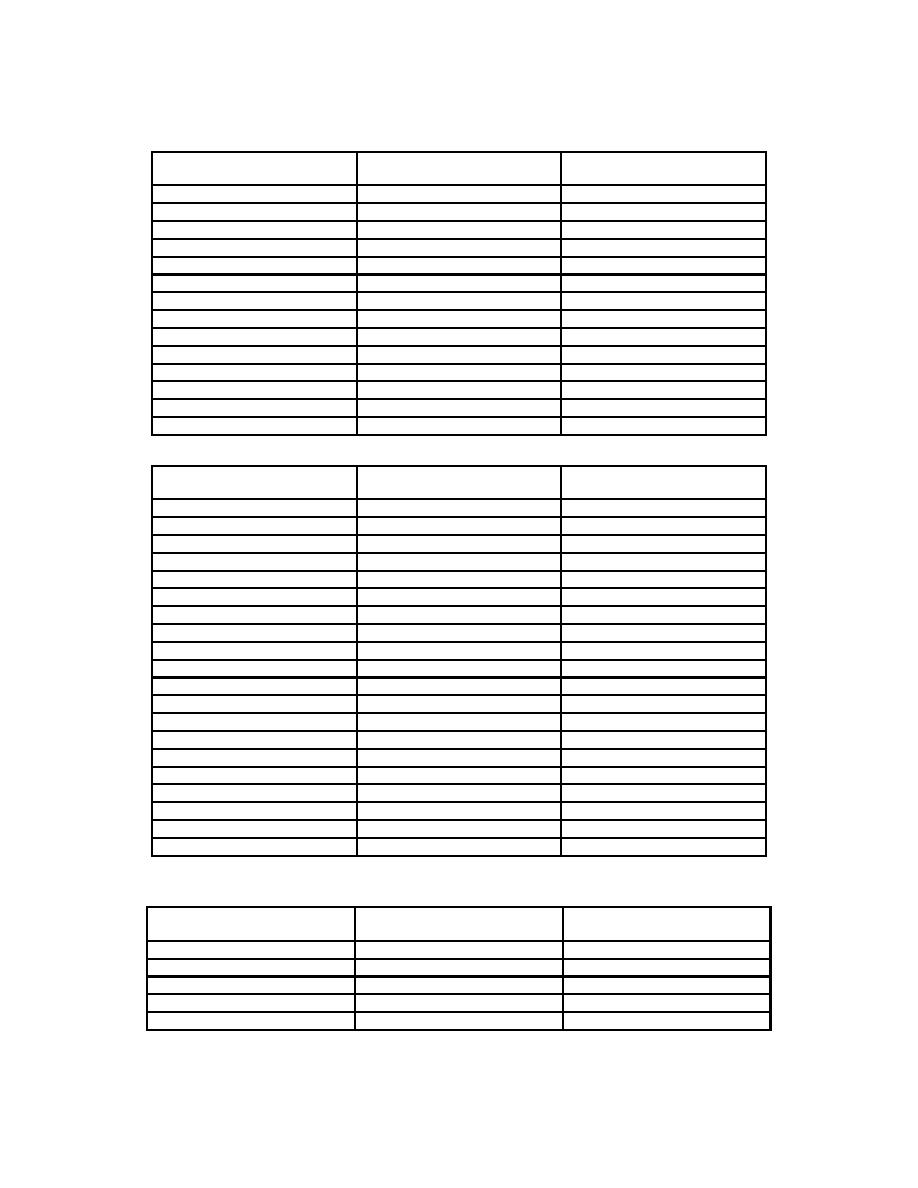
TB 9-6625-2358-35
RF power meter / calorimeter
Band pass filter band
difference indication (W)
setting (MHz)
5
∠ 4%
1.8
5
∠ 4%
2.0
6
∠ 4%
2.5
6
∠ 4%
3.2
7
∠ 4%
4.0
7
∠ 4%
5.0
8
∠ 4%
6.3
9
∠ 4%
7.9
9
∠ 4%
10.0
10
∠ 4%
13.0
10
∠ 4%
16.0
11
∠ 4%
20.0
11
∠ 4%
25.0
12
∠ 4%
32.0
Table 5. Directional Power Sensor Model 4022
RF power meter / calorimeter
Band pass filter band
difference indication (W)
setting (MHz)
11
∠ 4%
25
12
∠ 4%
30
12
∠ 4%
40
13
∠ 4%
50
13
∠ 4%
70
14
∠ 4%
90
14
∠ 4%
100
15
∠ 4%
110
15
∠ 4%
150
16
∠ 4%
190
16
∠ 4%
270
1
17
∠ 4%
400
17
∠ 4%
500
17
∠ 4%
600
18
∠ 4%
710
18
∠ 4%
750
18
∠ 4%
800
18
∠ 4%
900
18
∠ 4%
950
18
∠ 4%
1000
1Turn off signal generator output and change RF power amplifier band to HIGH.
Table 6. Directional Power Sensor Model 4025
RF power meter / calorimeter
Band pass filter band
difference indication (W)
setting (MHz)
1
∠ 4%
.100
1
∠ 4%
.135
2
∠ 4%
.300
3
∠ 4%
.500
3
∠ 4%
.600
Table continued on next page.
6


