
TB 9-6625-2364-24
a. Performance Check
(1) Set power meter power OFF ON pushbutton to OFF position.
(2) Disconnect thermistor mount from power meter interconnect cable.
(3) Connect multimeter (resistance mode) between VRF terminal center conductor
on power meter (rear panel) and pin 1 of thermistor mount end of power meter interconnect
cable.
(4) Round off multimeter indication to two decimal places and record this value as
power meter internal bridge resistance R (value will be approximately 200 Ω).
(5) Connect thermistor mount to power meter interconnect cable.
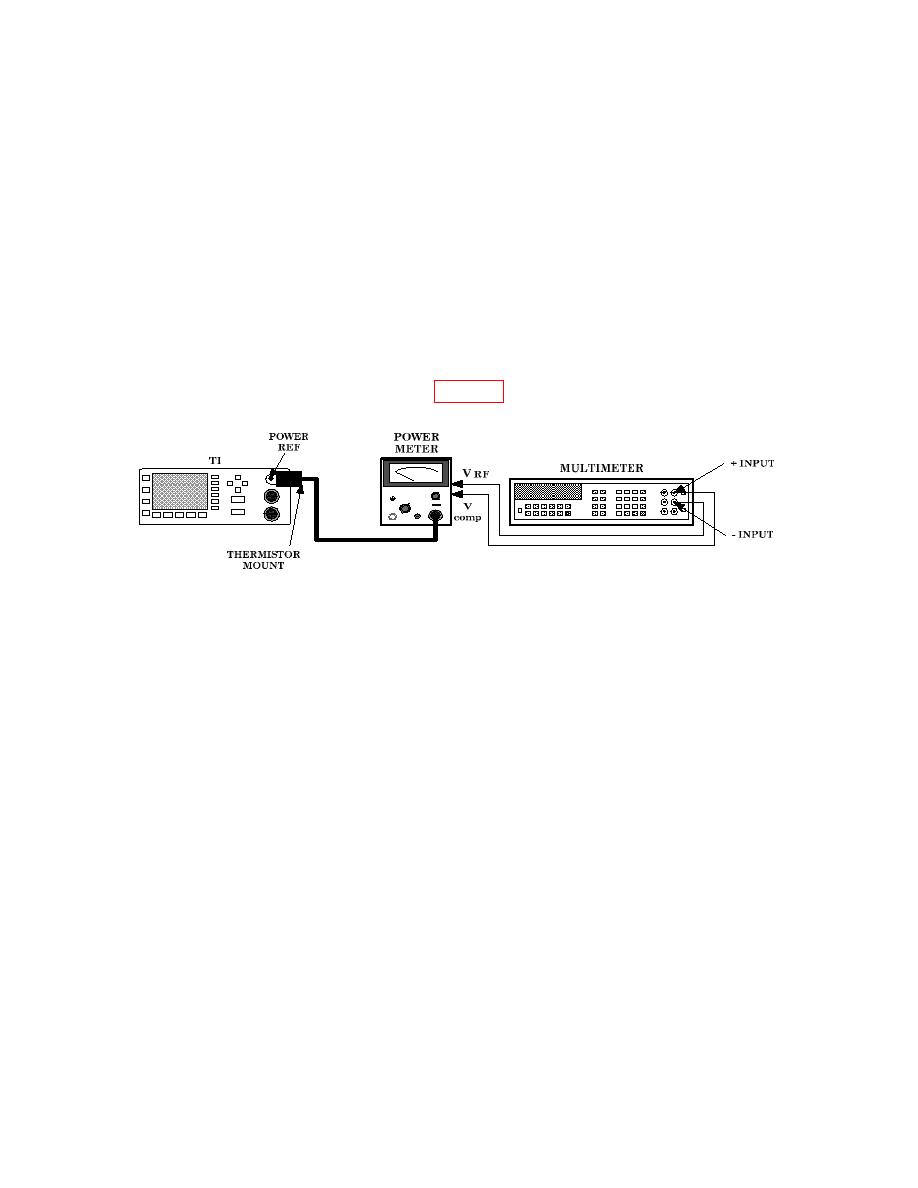
(6) Connect equipment as shown in figure 3.
(7) Set power meter OFF ON pushbutton to ON position.
(8) Set TI POWER switch to on and press Preset Local, [Confirm] keys.
(9) Set power meter RANGE switch to COARSE ZERO and adjust front panel
COARSE ZERO control for a zero meter indication.
(10) Fine zero power meter on most sensitive range then set power meter RANGE
switch to 1 mW.
(11) Ensure multimeter input terminals are isolated from chassis ground for (12)
below.
(12) Adjust multimeter (dc mode) controls to measure microvolts.
(13) If multimeter indication is 400 V or less, record multimeter indication and
proceed to (15) below; if not, proceed to (14) below.
(14) Hold power meter FINE ZERO CONTROL and adjust COARSE ZERO control
for a multimeter indication 200 V or less. Record multimeter indication.
(15) Round off indications recorded in (13) or (14) above to two decimal places and
record this value as V0.
(16) Set power meter to highest range.
