TB 9-6625-781-24
FREQUENCY COUNTER
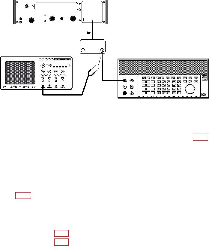
5245L OR 5245M
00000000
EXTENDER CABLE
TEST INSTRUMENT
OSCILLOSCOPE
OSCILLOSCOPE CALIBRATOR
1
1
CONNECT BETWEEN CENTER CONDUCTOR ON REAR OF STOP
INPUT CONNECTOR AND CHASSIS GROUND
Figure 6. Attenuator compensation - equipment setup.
(2) Adjust oscilloscope calibrator frequency to 10 kHz and output to 300 mV p-p as
indicated on oscilloscope.
(3) Disconnect cable from STOP connector and connect it to test point A4E1 (fig. 4).
Note waveforms displayed on oscilloscope.
(4) Set STOP MULTIPLIER switch to .2. If waveform observed on oscilloscope is
not as noted in (3) above, except reduced in amplitude by one-half, perform b (1) below.
(5) Disconnect cable from test point A4E1, and connect it to center conductor of
START connector and chassis ground.
(6) Connect oscilloscope calibrator to START connector and repeat (2) above.
(7) Disconnect cable from START connector, and connect it between test point
A3E1 (fig. 5) on start channel board and chassis ground. Note waveform displayed on
oscilloscope.
(8) Set START MULTIPLIER switch to .2. If waveform observed on oscilloscope is
not as noted in (7) above, except reduced in amplitude by one-half, perform b (2) below.
b. Adjustments
(1) Adjust A2C9 (fig. 4) to meet requirements of a (4) above (R).
(2) Adjust A1C9 (fig. 5) to meet requirements of a (8) above (R).
12

