
TB 9-6625-975-35
(2) Remove short and reconnect resistance standard, rotate generator crank cw at
normal speed and adjust R2 (fig. 3) for 50 MΩ .045 inches.
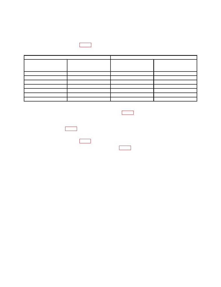
Table 5. Resistance Accuracy
Test Instrument
Resistance Standard Indications1
Range
Switch
Indications
Min
Max
Settings
8
12
MΩx1
MΩ
MΩ
MΩ
10
19
21
MΩx1
MΩ
MΩ
MΩ
20
28
32
MΩx1
MΩ
MΩ
MΩ
30
45
55
MΩx1
MΩ
MΩ
MΩ
50
38
42
MΩx2
MΩ
MΩ
MΩ
40
9.5
10.5
MΩ 2
MΩ
MΩ
MΩ
10
950
1050
MΩ 5
kΩ
Ω
Ω
11
1Substitute
resistance standards as required for MΩ indications.
(3) Repeat (1) and (2) above and adjust R2 (fig. 3) for best compromise or until no
further adjustments are required.
(4) With TI HI and LO terminals shorted rotate generator crank cw at normal
speed and adjust R1 (fig. 3) for 0 .045 inches.
(5) Remove short and reconnect resistance standard, rotate generator crank cw at
normal speed and adjust R1 (fig. 3) for 50 MΩ .045 inches.
(6) Repeat (4) and (5) above and adjust R1 (fig. 3) for best compromise or no further
adjustments are required.
17. Final Procedure
a. Deenergize and disconnect all equipment and reinstall protective cover on TI.
b. Annotate and affix DA Label/Form in accordance with TB 750- 25.
12
