
TB 9-6695-242-24
usage accessories issued as indicated in paragraph 4 above, and are not listed in this
calibration procedure.
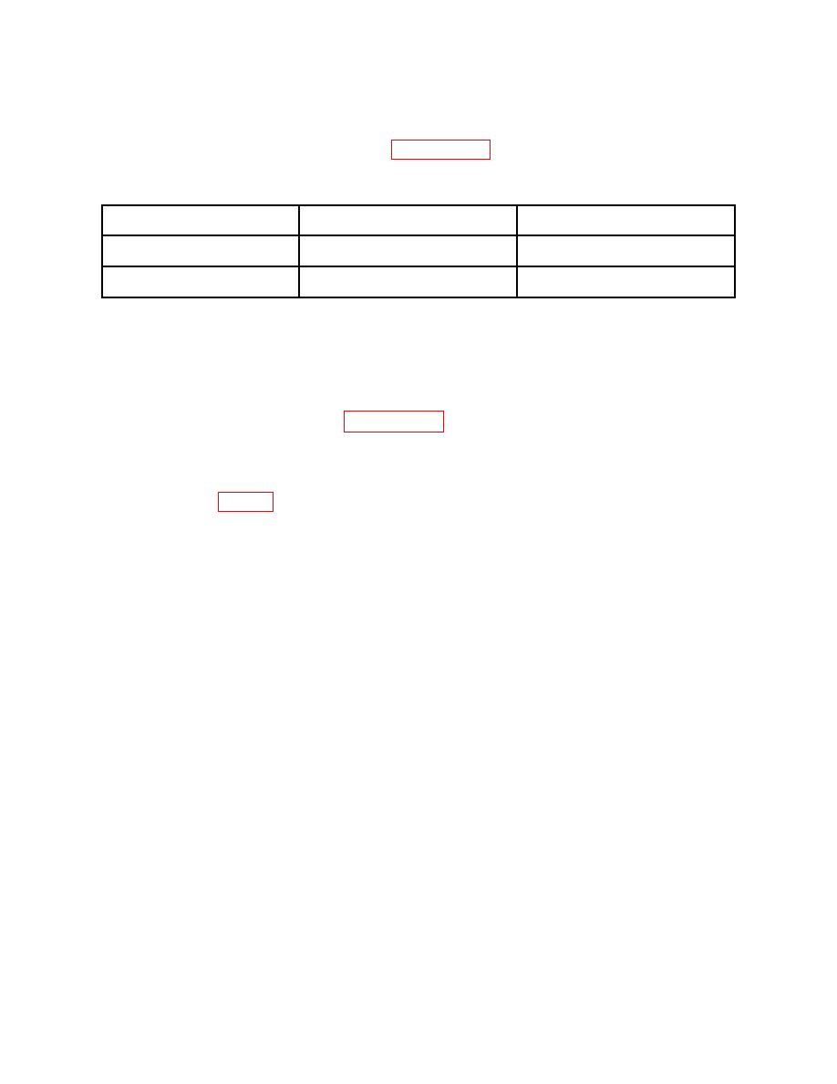
Manufacturer and model
Common name
Minimum use specifications
(part number)
LOAD CELL INDICATOR
Range: 175 to 20,400 lbs
HBM, Model MGCplus (13589298)
Accuracy: 0.05% of reading
LOAD CELL
Range: 900 to 20,400 lbs
Revere Corporation, USP1-20B
1
(MIS-26331TY3)
Accuracy: 0.25% FS
1Limited
deployment item.
6. Preliminary Instructions
process. Personnel should become familiar with the entire bulletin before beginning the
calibration.
b. Items of equipment used in this procedure are referenced within the text by common
name as listed in table 2.
c. Unless otherwise specified, verify the result of each test and, whenever the test
requirement is not met, take corrective action before continuing with the calibration.
Adjustments required to calibrate some models of the TI are included in this procedure.
Additional maintenance information is contained in the manufacturer's manual for this TI.
d. Unless otherwise specified, all controls and control settings refer to the TI.
7. Equipment Setup
HIGH VOLTAGE is used or exposed during the performance of
this calibration.
DEATH ON CONTACT may result if
personnel fail to observe safety precautions.
REDUCE
OUTPUT(S) to minimum after each step within the
performance check where applicable.
a. Visually inspect TI for any damage that will affect measuring accuracy.
b. Check that TI clevis pivots freely and easily on shackle.
c. Tighten two locking screws on back of TI.
CAUTION
Locking screws must be tight to prevent damage to gage
movement.
d. Adjust zero-adjusting screw (located in slot on side of TI) until pointer indicates zero.
