
TB 9-6695-301-50
7. Equipment Setup
a. Verify TI is clean and free from defects that would impair its operation.
b. Allow equipment to stabilize to ambient temperature.
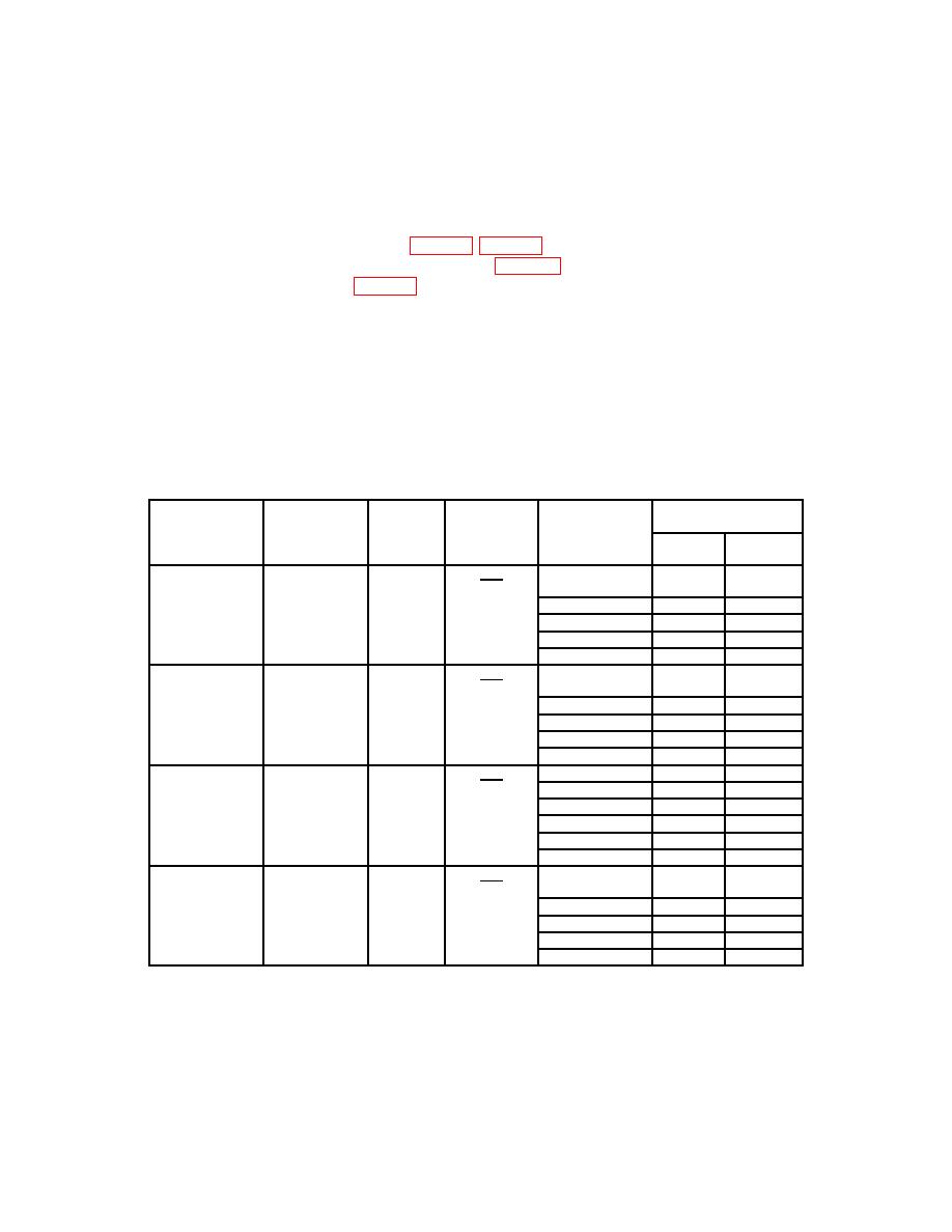
Calculate torque for cardinal points listed in table 4 for each TI. Use CALCULATED
TORQUE formula shown after table 3.
NOTE
If the arm lengths are correct to: (.02-in. for 40-in. arm); (.005-
in. for 10-in. arm); and (.0015-in. for 2.5-in. arm); then nominal
values may be used for length and the equation becomes:
T = Nominal length x weight corrected for local gravity.
Test
Actual
Tolerance range
instrument
Weight
weight1
Calculated2
Min
Max
range
calibrator
(lbs)
(lbs)
torque
(-0.5%)
(+0.5%)
Model
lbs
0 to 60 in-lb
60 STPI
5
0 to 5 ft-lb
(2.5-in.
10
radius)
15
20
Full scale
24
Model
lbs
0 to 20 ft-lb
2000 STPI
5
0 to 240 in-lb
(10-in.
10
radius)
15
20
Full scale
24
Model
lbs
0 to 100 ft-lb
2000 STPI
24
0 to 1200 in-lb
(10-in.
48
radius)
72
96
Full scale
120
Model
lbs
0 to 500 ft-lb
STPI
30
(40-in.
60
radius)
90
120
Full scale
150
See footnotes at end of table.
