TB 9-6920-430-50
1/ and 9/ inch wrenches; tighten securely. Set aside transducer fitting protective cap.
2
16
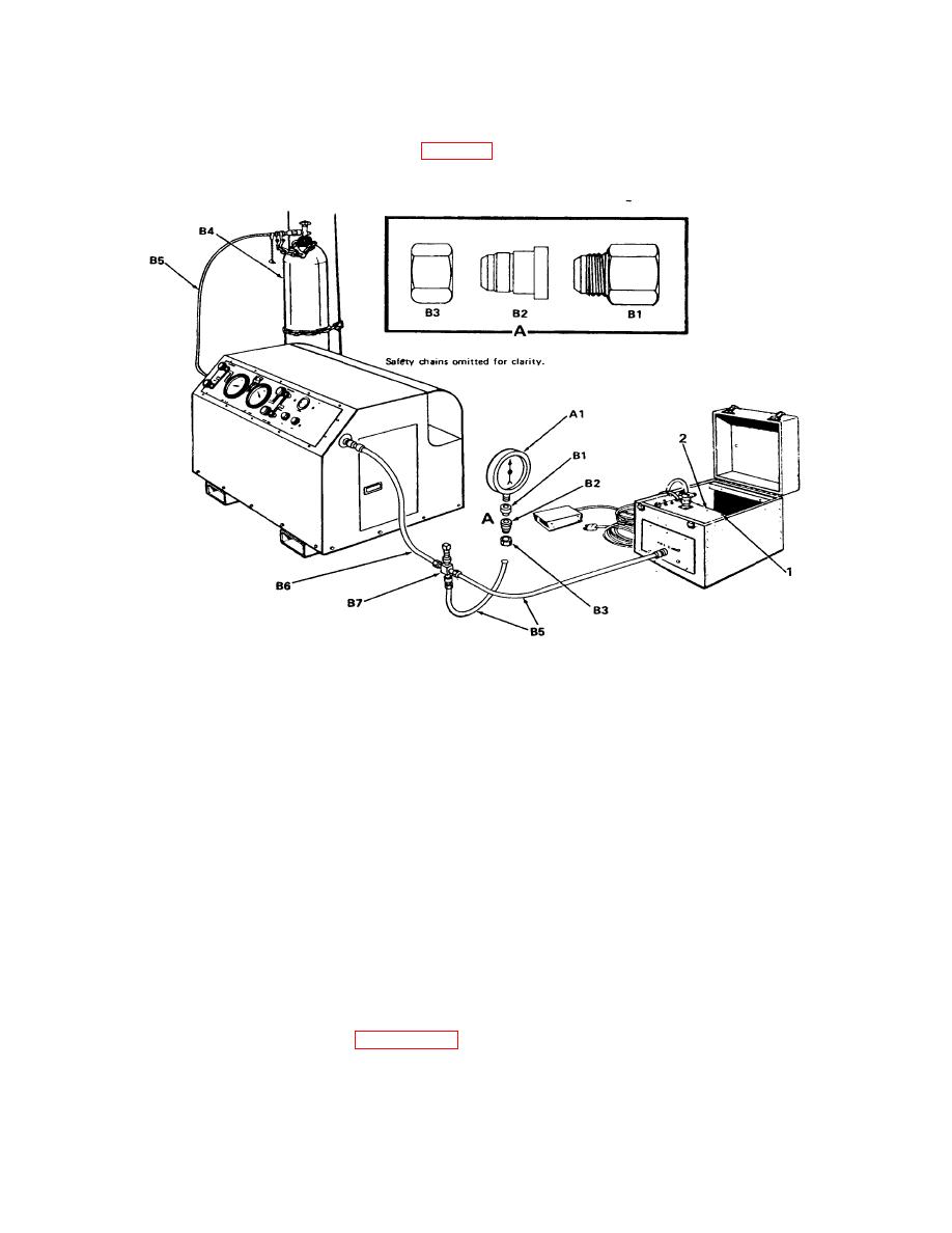
Figure 1. Equipment Setup.
c. Open the TI lid and remove the digital readout with its cable. Connect the digital
readout cable to the TI. Place the digital readout next to the test gage (A1).
d. On the GPU, close (CW) the INLET SHUTOFF, INLET BLEED, OUTLET
SHUTOFF, and OUTLET BLEED valves.
e. Very slowly open (CCW) the valve on the gas supply bottle (B4).
f. Using leak detecting liquid (B8), squirt some drops around all input gas system
fittings.
WARNING
Do not attempt to tighten fittings with system pressurized.
Serious injury can result if the high pressure fittings are
loosened instead of tightened.
g. Visually check for gas bubbles indicating leakage. If leaks are detected, perform
step 7h below. If not, perform paragraph 8 below.
5


