
f. Set sweep oscillator LINE switch to RF and
(6) Set UUT frequency range switch to
2-4 GHz.
allow a 15-minute warmup.
(7) Replace attenuator (1-4) with attenua-
tor (1-5).
a. Performance Check.
(8) Slowly turn sweep oscillator START/
CW control from 2.0 to 4.0 GHz. Record power
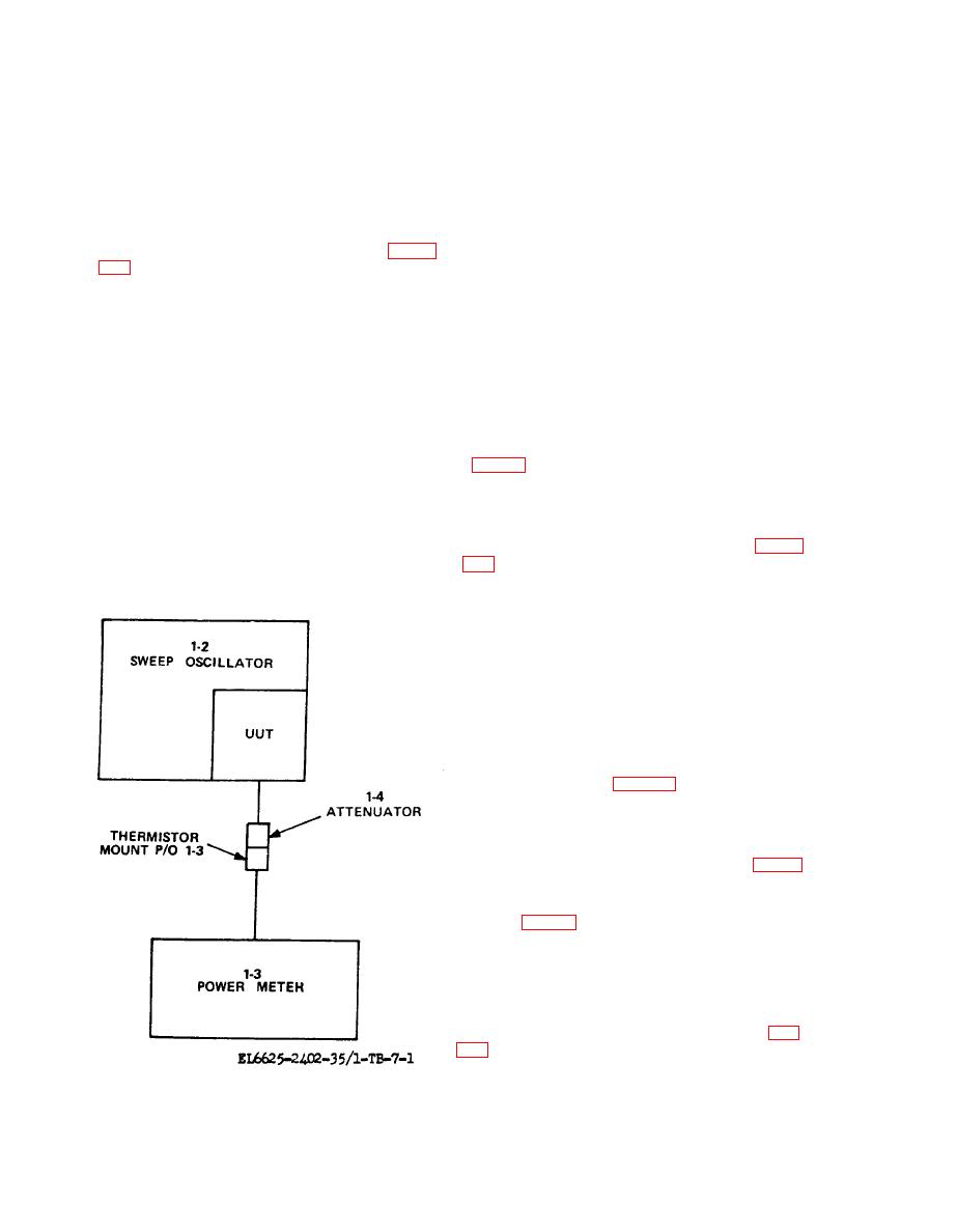
(1) Connect equipment as shown in figure
meter minimum and maximum indications.
(9) Minimum power meter indication is
(2) Position sweep oscillator controls as fol-
greater than -12 dbm. Maximum indication does
lows:
not exceed minimum by more than 14 db.
(a) SWEEP SELECTOR switch to CW.
(b) ALC pushbutton released.
b. Adjustments.
(c) FUNCTION START STOP push-
(1) Repeat performance check steps (1)
button pressed.
through (3).
(d) All AMPLITUDE MOD pushbuttons
released.
(2) Adjust sweep oscillator START/CW con-
trol for minimum indication on power meter.
(3) Position UUT controls as follows:
( 3 ) Adjust UUT POWER ADJ AlR40
(a) Frequency range switch to .1-2 GHz.
(b) POWER LEVEL control fully clock-
wise.
(4) Slowly turn sweep oscillator START/
CW control from 0.1 to 2.0 GHz. Record power
a. Performance Check.
meter minimum and maximum indications.
(1) Connect equipment as shown in figure
(5) Minimum power meter indication is
greater than -7 dbm. Maximum indication does
(2) Position sweep oscillator controls as fol-
not exceed minimum by more than 14 db.
lows:
(a) SWEEP SELECTOR switch to CW.
(b) FUNCTION START STOP pushbut-
ton pressed.
(C) All AMPLITUDE MOD pushbuttons
released.
(d) ALC pushbutton released.
(3) Turn UUT POWER LEVEL control
fully clockwise.
(4) Turn sweep oscillator START/CW con-
trol to settings listed in table 7-2. Set UUT fre-
quency range switch as listed. Electronic counter
(1-7) indicates within specified limits.
b. Adjustments.
(1) Connect equipment as shown in figure
7-3.
(2) Connect multimeter (1-8) between UUT
A1TP5 (fig. 7-2) and chassis ground with cable
assembly ( 1-9).
(3) Set UUT frequency range switch to 2-
4 GHz.
(4) Adjust sweep oscillator START CW
control for multimeter indication of 3.00 wit.
(5) Adjust UUT 2.0 GHz ADJ AIR28 (fig.
GHz.
(6) Adjust sweep oscillator START CW
control for multimeter indication of 73.00 vdc.
42

