
nector to voltmeter (1-12) with cable assembly
(a) FUNCTION START-STOP pushbut-
(1-5) and termination (1-13).
ton pressed.
( b ) SWEEP SELECTOR switch to
(2) Position sweep oscillator controls as fol-
AUTO.
lows:
(c) START/CW control to 1 (4 on PL-
(a) FUNCTION START-STOP pushbut-
1241A/USM-308(V)).
ton pressed.
(d) STOP/ F control to 100.
(b) SWEEP SELECTOR switch to CW.
(e) SWEEP TIME (SEC) switch to .1-
(c) START/CW control to 40.
.01.
(3) Position UUT controls as follows:
(3) Position UUT controls as follows:
(a) SCALE switch to X1.
(a) SCALE switch to X1.
(b) POWER LEVEL switch to + 10DBM.
(b) POWER LEVEL switch to 0DBM,
(c) VERNIER control fully clockwise.
(c) VERNIER control to CAL.
(4) Voltmeter indicates greater than 2.23
(4) Adjust signal generator (1-6) controls
vrms (between 0.19 and 0.26 vac on PL-1241A/
for output meter indication of 1.0 vrms and elec-
USM-308(V)).
tronic counter indication of 1.0000 MHz.
(5) Turn UUT VERNIER control to CAL.
(5) Adjust oscilloscope (1-11) controls for
(6) Set UUT POWER LEVEL switch to
horizontal display of first marker on extreme left
settings listed in table 6-5. Voltmeter indicates
graticule line and last marker on extreme right
within specified limits.
graticule line.
(7) Disconnect equipment.
(6) .Markers occur within -0.5 and +0.5
b. Adjustments.
mm of every 1 cm calibration line on horizontal
axis.
(1) Position UUT controls as follows:
(a) POWER LEVEL switch to +10 dbm.
(7) Set UUT SCALE switch to X1
(b) VERNIER control fully counterclock-
(8) Adjust signal generator controls for out-
wise.
put meter indication of 1.0 vrms (3.0 vrms on
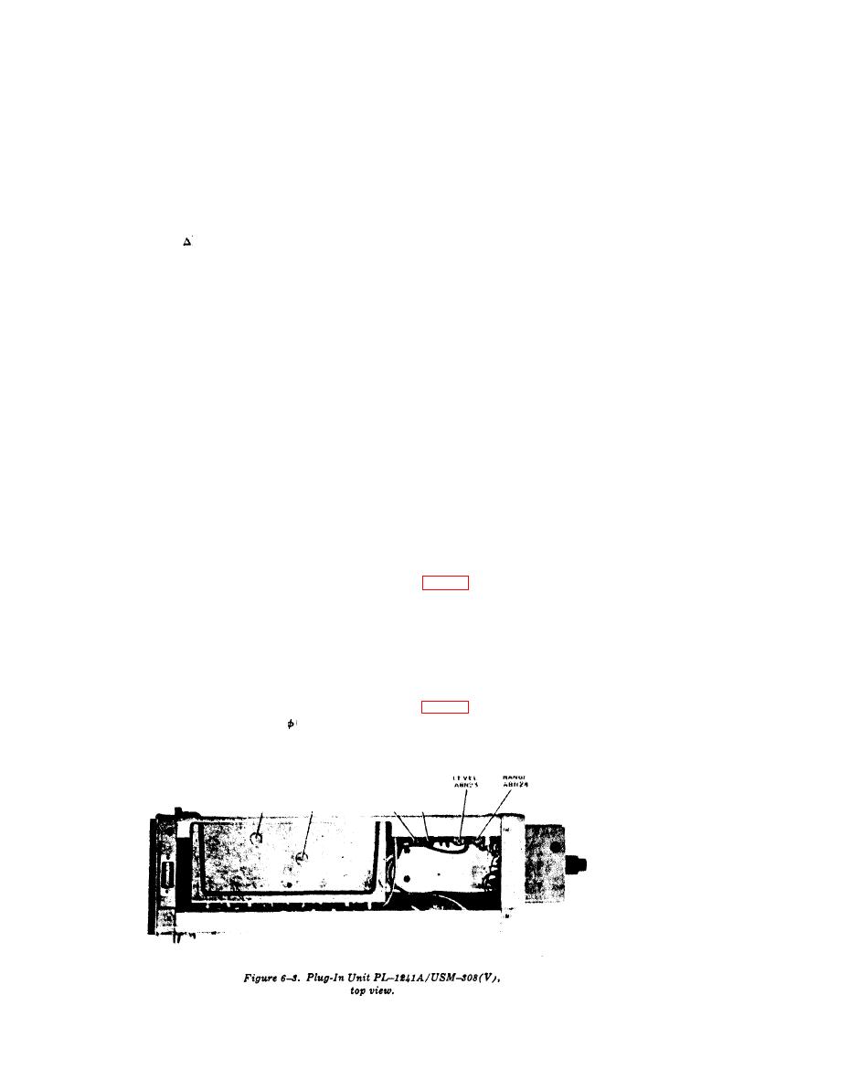
(2) Adjust UUT RANGE adjustment, A8-
PL-1241A/USM-308(V)) and electronic counter
R24 (fig. 6-3) for voltmeter indication of 0.223
indication of 10.000 MHz.
vat.
(9) Repeat steps (5) and (6) above.
NOTE
(10) Disconnect equipment.
Earlier models may not have this adjust-
b. Adjustments. No adjustments can be made.
ment.
(3) Turn UUT VERNIER control to CAL
(4) Adjust UUT LEVEL adjustment, A8-
a. Performance Check.
R23 (fig. 6-3) for voltmeter indication of 0.707
(1) Connect UUT OUTPUT 50 (ohm) con-
vat.
EL6625-2402-35/1-TB-6-3
36

