
TB 9-5855-1892-24
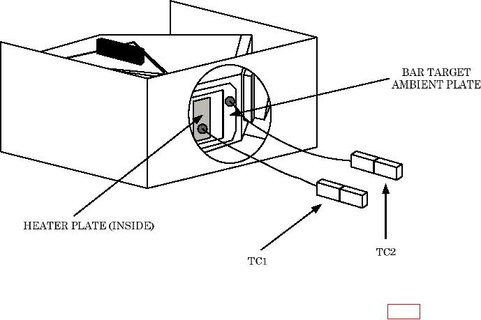
Figure 6. Thermocouple to heater plate setup.
d. Repeat technique of c (1) through (3) above for thermocouple TC2 (fig. 6).
e. Connect thermocouple wires to multimeter input HI (TC1) and input LO (TC2) terminals.
NOTE
TC1 is labeled with a + sign.
NOTE
Verify thermocouple leads have not moved and are still located
in thermally conductive paste and are not touching sides of
BAR TARGET window.
f. Ensure TI ON/OFF switch is in OFF position.
g. Connect multimeter to 115 V ac power source, turn power on, and allow time for
multimeter to warm-up and stabilize.
9. Temperature Check
a. Performance Check
(1) Set TI ON/OFF switch to ON (green READY lamp will momentarily illuminate).
(2) Wait for READY lamp to illuminate and remain illuminated for a minimum of
8 minutes.
(3) Perform steps (a) through (g) below:
(a) Monitor multimeter indications for a minimum of 2 minutes.

