
TB 9-5855-1892-35
(f) Verify digital multimeter indication is 15 2 V dc.
(2) Perform steps in (a) through (f)(2) below:
(a) Set TI ON -OFF switch to OFF position.
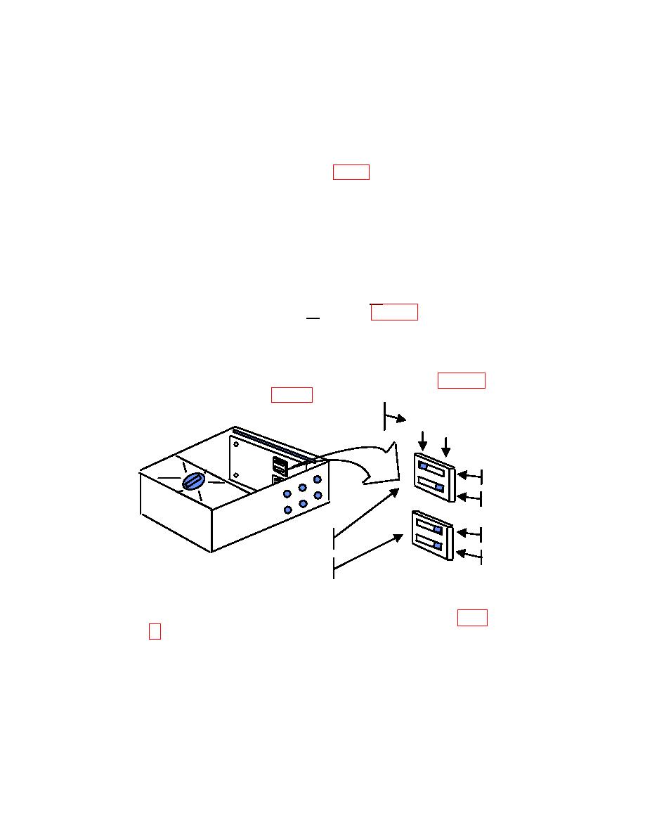
(b) Remove LARGE COVER PLATE (fig. 2).
(c) Ensure ON ALIGN switch is set to ON.
CAUTION
Disconnect ac power cable from TI before changing dip switch
settings and reconnect TI to ac power cable after changing dip
switch settings.
NOTE
Ensure Dip Switch 1, A and B are set to on. Ensure Dip
Switch 2, C and D are set to on. Refer to figure 9 for example
of settings.
(d) Refer to calculated temperature error for BAR target recorded on BAR
Target Temperature Worksheet or for MRT target recorded on MRT Target Temperature
Worksheet and set DIP SWITCH 1 and DIP SWITCH 2 (example in figure 9) to indicate
temperature error C as indicated in table 4 (R).
DIP SWITCH SETTINGS
ON CIRCUIT CARD
OFF
ON
A
B
C
DIP SWITCH
1
D
DIP SWITCH
2
NOTE
A temperature correction greater than limits specified in table
each time technique of 9b(2) is performed depending on dip
switch settings. Repeating technique of 9b(2) will cause
additional temperature corrections each time the step is
performed.
12

