
TB 9-6625-1314-35
(6) Remove short connected in (2) above.
(7) Connect dc voltage standard (A7) for Level A and AN/GSM-259 calibration or
electrical test set (A11) and ac/dc voltmeter (A3) for AN/GSM-256 and AN/TSM-55
calibration to TI INPUT terminals using leads (B4).
(8) Adjust output of dc voltage standard or electrical test set to obtain an indication
of 99.99 on TI. If dc voltage standard or ac/dc voltmeter does not indicate between 99.880
and 100.10 mV, perform b(7) through (35) below.
(9) Adjust autotransformer between 105 and 125 V while repeating technique of (8)
above. Dc voltage standard on ac/dc voltmeter indication will remain between 99.880 and
100.10 mV.
(10) Adjust autotransformer to 115 V.
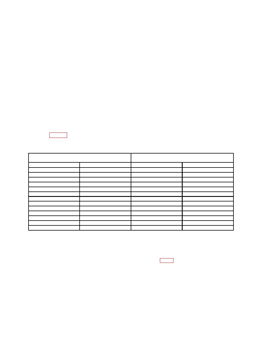
(11) Repeat technique of (8) above using RANGE switch settings and indications
listed in table 6. If dc voltage standard or ac/dc voltmeter does not indicate within limits
specified, perform b(7) through (35) below.
Table 6. Dc Volts
Dc voltage standard or ac/dc
Test instrument
voltmeter indication (V dc)
Indication
Min
Max
RANGE switch
1000 MV
999.9
0.99880
1.0010
10 V
9.999
9.9930
10.0050
10 V
9.000
8.9945
9.0055
10 V
8.000
7.9950
8.0050
10 V
7.000
6.9955
7.9945
10 V
6.000
5.9960
6.0040
10 V
5.000
4.9965
5.0035
10 V
4.000
3.9970
4.0030
10 V
3.000
2.9975
3.0025
10 V
2.000
1.9980
2.0020
10 V
1.000
0.9985
1.0015
100 V
99.99
99.930
100.050
1000 V
999.9
999.30
1000.50
b. Adjustments
(1) Position rear panel ZERO adjust to its mechanical midposition.
(2) Adjust A2R70 COMPARATOR BALANCE ADJ (fig. 1) to obtain an indication of
0.000 on TI (R).
10

