
TB 9-6625-134-24
(26) Set calibrator as listed in (a) through (c) below.
(a) 9, 0, 0, m, V.
(b) 6, 0, Hz.
(c) OPR/STBY to OPR.
(27) If selected TI A/B readout is not within limits listed in table 9 perform b below.
(28) Repeat technique of (25)(k) through (27) above for remaining rows in table 9. If
TI readout is not within limits listed in table 9 perform b below.
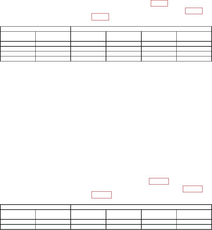
Table 9. Oscilloscope Readout ACV AC Coupled Low Frequency.
Calibrator
TI
Output Level
Channel Input
Range
Minimum
Maximum
(mV)
(Hz)
(mV/div)
(mV)
(mV)
900
60
B
500
873
927
900
50
B
500
877
924
900 1
50
A
500
877
924
900
60
A
500
873
927
Set calibrator output to STBY and move connection from B INPUT to A INPUT and press A.
1
(29) Reduce calibrator output to minimum.
(30) Press TI keys as listed in (a) through (h) below.
(a) SCOPE.
(b) F2 READING, F1 to select READINGS 1, using
Keys select
on A, and PEAK...., ENTER.
Keys select Peak-Peak, ENTER.
(c) Using
(d) F2 READING, F1 to select READINGS 2, using
Keys select
READINGS 2, on B, ENTER, and PEAK...., ENTER.
Keys select Peak-Peak, ENTER, CLEAR to exit
(e) Using
softkey menu.
(f) s TIME ns, to select 1 mS/div.
(g) A, using MOVE move the Input A ground level to the center grid line.
(h) Using mV RANGE V to set the Input A sensitivity to 100mV/div.
(31) Set calibrator as listed in (a) through (c) below.
(a) 212.13 mV.
(b) 1, kHz.
(c) OPR/STBY to OPR.
(32) If the selected TI readout is not within limits listed in table 10 perform b below.
(33) Repeat technique of (30)(g), (31) and (32) above for remaining row in table 10. If
TI readout is not within limits listed in table 10 perform b below.
Table 10. Oscilloscope Readout Peak - Peak.
Calibrator
TI
Output Level
Range
Minimum
Maximum
Channel Input
(mV)
(kHz)
(mV/div)
(V)
(V)
212.13
1
A
100
0.56
0.64
1
212.13
1
B
100
0.56
0.64
Reduce calibrator output to minimum and move connection from B INPUT to A INPUT.
1
(34) Reduce outputs to minimum and disconnect equipment setup.
(35) Connect TI INPUT A and INPUT B to oscilloscope calibrator CHAN 1 and
CHAN 2 respectively.
13

