
TB 9-6625-1982-24
37. Frequency and Sensitivity (Prescale Input)
a. Performance Check
(1) Set RESOLUTION switch to PRESCALE 100 Hz and connect signal
generator RF OUTPUT to TI prescale INPUT, using adapter and cable.
(2) Adjust signal generator frequency to 100 MHz and amplitude to minimum.
(3) Slowly increase signal generator amplitude until TI displays a stable count. If
signal generator does not indicate 20 mV or less, perform b below.
(4) Repeat technique of (2) and (3) above at 250 MHz, 500 MHz, and 1.0 GHz. If
signal generator does not indicate 20 mV or less, perform b below.
(5) (DC508AOPT01 only) Repeat technique of step (3) above at 1.1 GHz and
1.3 GHz. Signal generator must indicate 40 mV rms or less.
b. Adjustments
(1) Adjust signal generator frequency for 500 MHz and amplitude to 9 mV (R).
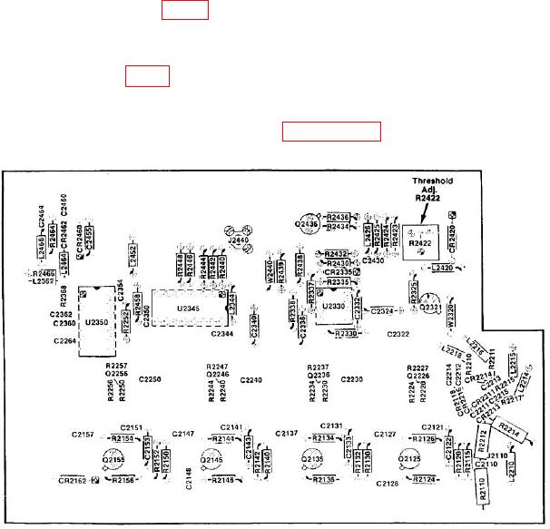
(2) Adjust R2422 (fig. 7) CCW until INPUT OUT OF RANGE light illuminates,
then adjust CW until light just extinguishes. (R)
NOTE
R2422 (fig. 7) may be readjusted as necessary for stable
indication with 20 mV rms or less input.
(3) If adjustments were made repeat paragraph 37 a (1) through (5).
Figure 7. Prescale - types DC508, DC508OPT01, and DC508AOPT01.

