
TB 9-6625-2071-24
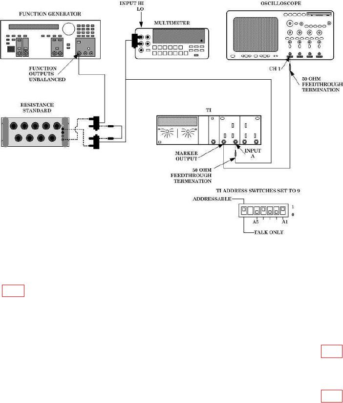
Figure 6. Trigger Level Adjustment - Equipment Setup.
(8) Move oscilloscope Vertical 1 connection from TI CHANNEL A MARKER
OUTPUT to TI CHANNEL B MARKER OUTPUT.
(9) Adjust oscilloscope controls as necessary to view waveform. Adjust A11R20
(fig. 1) for a 50 percent duty cycle on oscilloscope display.
(10) Execute TI command string: PF4G6S1S3A379+200*B37+200*R.
(11) Set function generator Offset to +2 V dc.
(12) Adjust resistance standard and function generator offset until multimeter
indicates +2.000 V dc 0.002 V dc.
(13) Adjust oscilloscope controls as necessary to view waveform. Adjust A11R18 (fig. 1)
for a 50 percent duty cycle on oscilloscope display.
(14) Move oscilloscope Vertical 1 connection from TI CHANNEL B MARKER
OUTPUT to TI CHANNEL A MARKER OUTPUT.
(15) Adjust oscilloscope controls as necessary to view waveform. Adjust A11R24 (fig. 1)
for a 50 percent duty cycle on oscilloscope display.
(16) Execute TI command string PF4G6S1S3A379-200*B37-200*R.
(17) Set function generator Offset to -2 V dc.
16

