
TB 9-6625-2114-24
(2) Connect AC PROBE tip and ground clip lead together and adjust AC ZERO for
0 indication on TI.
(3) Connect TI AC PROBE tip and ground clip lead to calibrator OUTPUT HI and LO.
(4) Set calibrator output frequency to 400 Hz and amplitude for a 0.3 V ac indication
on TI.
(5) Press calibrator NEW REF key.
(6) Set calibrator frequency to 20 Hz. Using amplitude output adjustment controls,
adjust calibrator amplitude for a 0.3 V ac indication on TI. Calibrator control display Error
will indicate between 12.2% and +10.87% ( 1 dB).
(7) Repeat (6) above at 1 kHz, 100 kHz and 1 MHz.
(8) Adjust calibrator amplitude for a 0.00 ppm control display Error indication.
(9) Set calibrator to STANDBY and disconnect from TI.
NOTE
ZERO
If necessary,
perform
measuring
receiver
and
CALIBRATE.
(10) Connect measuring receiver sensor module input to calibrator OUTPUT HI and LO.
(11) Set calibrator to OPERATE.
(12) Set measuring receiver to measure RF power in dBm at 1 MHz. Record
measuring receiver indication.
(13) Set calibrator to STANDBY and disconnect from measuring receiver.
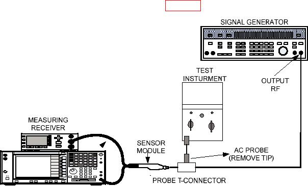
(14) Connect equipment as shown in figure 2.
Figure 2. Frequency response setup.
8

