
TB 9-6625-2139-24
(21) Set oscilloscope calibrator LEVEL SINE output to 60 MHz and approximately
50 mVpp for 1.0 division of vertical display on TI.
(22) Set A TRIGGER pushbutton to first row listed in table 19 and adjust A
TRIGGER LEVEL control to obtain a stable display. If a stable display cannot be
obtained, perform adjustments listed in table 19.
(23) Repeat technique of step (22) above for remaining A TRIGGER pushbutton
combinations listed in table 19. If a stable display cannot be obtained for each combination,
perform adjustments list in table 19.
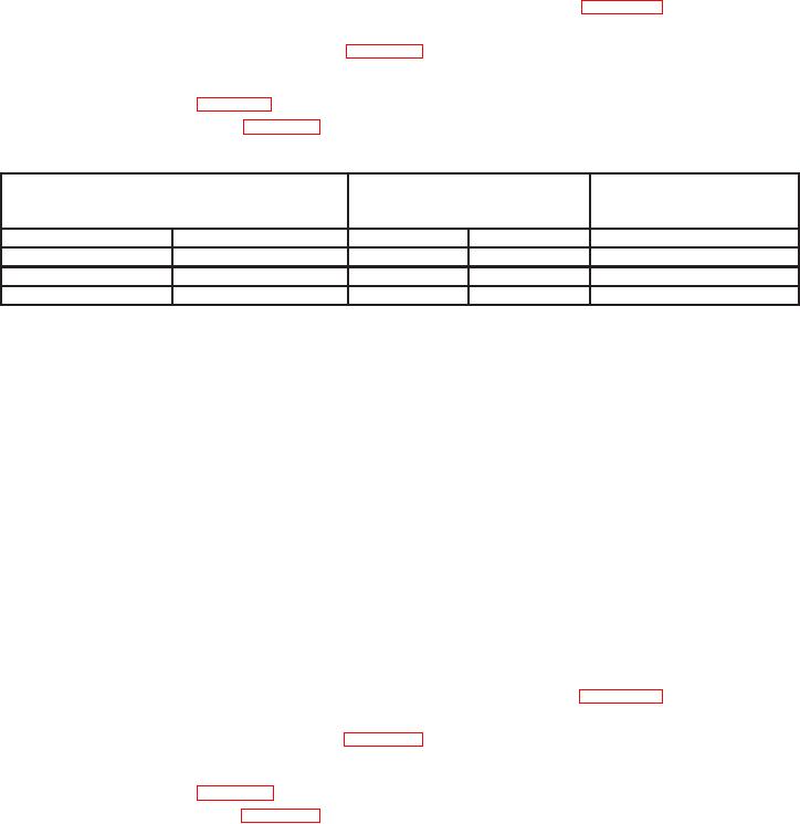
Table 19. A Trigger Level Channel 1
Test instrument
Test instrument
Test instrument
A TRIGGER LEVEL stable
A TRIGGER
adjustments
pushbutton combinations
display test
MODE
SLOPE
b
Yes
No
b
NORM
IN:
b
P-P AUTO
IN:
b
P-P AUTO
OUT:
(24) Set HORIZONTAL MODE switch to B adjust B INTENSITY control for
suitable viewing.
(25) Verify a stable display can be obtained by adjusting B TRIGGER LEVEL
control in a position other than B RUNS AFTER DLY; if not, perform b below.
(26) Press B TRIGGER SLOPE pushbutton to IN and verify a stable display can be
obtained by adjusting B TRIGGER LEVEL control in a position other than B RUNS
AFTER DLY; if not, perform b below.
(27) Position controls as listed in (a) through (d) below:
(a) VERTICAL MODE CH 1 BOTH CH 2 switch to CH 2.
(b) HORIZONTAL MODE switch to A.
(c) B TRIGGER SLOPE pushbutton to: OUT.
(d) Connect oscilloscope calibrator CHAN 1 to TI CH 2 using a 50 :
feedthrough termination.
(28) Set A TRIGGER pushbutton to first row listed in table 20 and adjust A
TRIGGER LEVEL control to obtain a stable display. If a stable display cannot be
obtained, perform adjustments listed in table 20.
(29) Repeat technique of step (28) above for remaining A TRIGGER pushbutton
combinations listed in table 20. If a stable display cannot be obtained for each combination,
perform adjustments list in table 20.
28

