
TB 9-6625-2139-24
(61) Press A TRIGGER NORM pushbutton. Next press in and hold TRIG VIEW
pushbutton and adjust A TRIGGER LEVEL control to obtain a stable display.
(62) Repeat technique of step (61) above for A TRIGGER pushbutton combinations
listed in table 25.
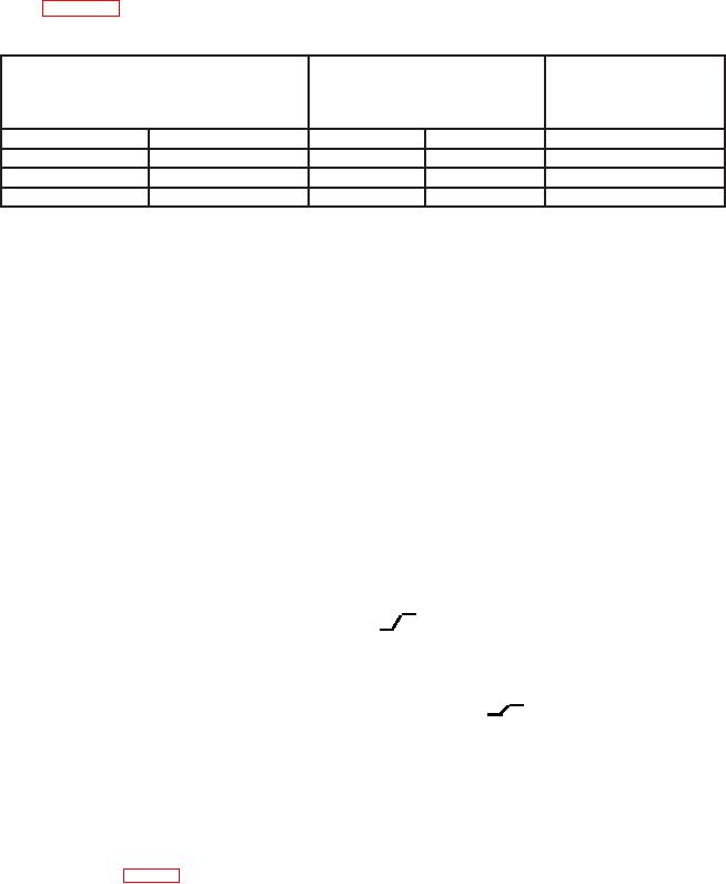
Table 25. A Trigger Level A Source to EXT INPUT
Test instrument
Test instrument
A TRIGGER LEVEL with
Test instrument
A TRIGGER
TRIG VIEW
adjustments
pushbutton combinations
in stable display test
MODE
SLOPE
b
YES
NO
b
NORM
IN:
b
P-P AUTO
IN:
b
P-P AUTO
OUT:
b. Adjustments
(1) Disconnect oscilloscope calibrator and 50 : feedthrough termination from TI.
(2) Position controls as listed in (a) through (o) below:
(a) POSITION controls to midrange.
(b) VERTICAL MODE CH 1 BOTH CH 2 switch to BOTH.
(c) VERTICAL MODE TRIGGER SOURCE CH 1 pushbutton to out position
(AN/USM-488).
(d) VERTICAL MODE TRIGGER SOURCE CH 2 pushbutton to in position
(AN/USM-488).
(e) VERTICAL MODE ADD ALT CHOP switch to ALT.
(f) CH 1 and CH 2 VOLTS/DIV switches to .5.
(g) CH 1 and CH 2 AC GND DC switches to GND.
(h) HORIZONTAL MODE switch to A.
(i) A AND B SEC/DIV switches to 1 ms.
B TRIGGER SLOPE to OUT:
(j)
(k) B TRIGGER LEVEL control to midrange.
(l) A TRIGGER P-P AUTO pushbutton pressed.
(m) A TRIGGER SLOPE pushbutton to OUT:
(n) A TRIGGER LEVEL control to midrange.
(o) A TRIGGER A&B INT switch to CH 2 (type 2235).
(3) Adjust CH 1 and CH 2 POSITION controls to set both traces to the center
horizontal graticule line.
(4) Connect multimeter LO to chassis ground and HI to pin 1 on A5 ALTERNATE
SWEEP BOARD (fig. 1) connector. Multimeter indication will be less than 100 mV dc.
Record multimeter indication.
32

