
TB 9-6625-2139-35
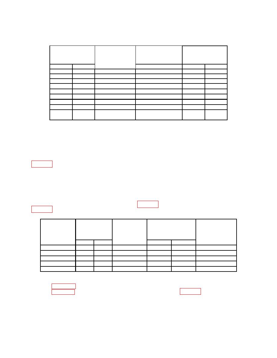
Table 14. B Sweep X10 Mag Timing Continued
Test instrument
Test instrument
linearity
SEC/DIV
calibrator
calibrator
0.1 division over any
switch settings
MARKER
Err display limits
2 center 8 divisions
%
A
B
output settings
Yes
No
10 S/D
.2 ms
.1 ms
3
20 S/D
.5 ms
.2 ms
3
50 S/D
1 ms
.5 ms
3
2 ms
1 ms
.1 mS/D
3
5 ms
2 ms
.2 mS/D
3
10
ms
5 ms
.5 mS/D
3
20
ms
10
ms
1 mS/D
3
50
ms
20
ms
2 mS/D
3
.1 sec
50
ms
5 mS/D
3
A ONLY
(30) Position controls as listed in (a) through (d) below:
(a)
Xl0 CAL control to in position.
(b)
B DELAY TIME POSITION dial to 1.00.
(c)
B TRIGGER LEVEL control fully cw.
(d)
A TRIGGER P-P AUTO pushbutton pressed.
(31) Set TI switch settings and oscilloscope calibrator out setting to first row listed in
(32) Adjust A TRIGGER LEVEL, B INTENSITY, and CH 1 POSITION controls
for suitable viewing.
(33) Adjust horizontal POSITION control to aline the first fully displayed time
marker with the center vertical graticule line.
(34) Adjust B DELAY TIME POSITION dial to approximately 9.00 to aline time
marker with the center vertical graticule line. B DELAY TIME POSITION dial
indication will be within dial limits listed in table 15, if not perform adjustments listed in
Test instrument
Test
B DELAY TIME
Test instrument
calibrator
instrument
POSITION
TIME/DIV
MARKER
VOLTS/DIV
Test instrument
dial limits
switch setting
output setting
switch setting
Min
Max
adjustments
A
B
.5 s
.05s
.5 s
.5
8.91
9.09
b(29) through (36)
5 s
.5 s
5 s
.5
8.91
9.09
b(29) through (36)
.5 ms 50 s
.5
.5 ms
8.91
9.09
b(29) through (36)
.5
5 ms
.5 ms
5 ms
8.91
9.09
b(29) through (36)
.5
.5 s
50 ms
.5 s
8.91
9.09
b(29) through (36)
1
A TRIGGER NORM pushbutton.
1Press
(35) Repeat technique of (32) through (34) above for settings listed in the remaining
rows of table 15. If B DELAY TIME POSITION dial indication is not within dial limits
21

