
TB 9-6625-2139-35
A AND B SEC/DIV switches to .2 s.
(c)
(d)
B DELAY TIME POSITION dial fully ccw.
(e)
B TRIGGER SLOPE pushbutton to OUT.
(f)
B TRIGGER LEVEL control to midrange.
(g)
A TRIGGER P-P AUTO pushbutton pressed.
(h)
A TRIGGER SLOPE pushbutton to OUT.
(i)
A TRIGGER LEVEL control to midrange.
(j)
A TRIGGER A TRIG BW switch to FULL (AN/USM-488).
(k)
A TRIGGER A&B INT switch to VERT MODE (type 2235).
(l)
A TRIGGER A SOURCE switch to INT.
(m)
A TRIGGER A EXT COUPLING switch to DC.
(2) Connect oscilloscope calibrator CHAN 1 to TI CH 1 using a 50Ω feedthrough
termination.
(3) Set oscilloscope calibrator LEVEL SINE output at 10 MHz and approximately
17 mVpp for 3.5 divisions (3.0 divisions for type 2235) of vertical display on TI.
(4) Set CH 1 VOLTS/DIV switch to 50m.
(5) Set A TRIGGER pushbutton to first row listed in table 17 and adjust A
TRIGGER LEVEL control to obtain a stable display. If a stable display cannot be
obtained, perform adjustments listed in table 17.
(6) Repeat technique of step (5) above for remaining A TRIGGER pushbutton
combinations listed in table 17. If a stable display cannot be obtained for each combination,
perform adjustments list in table 17.
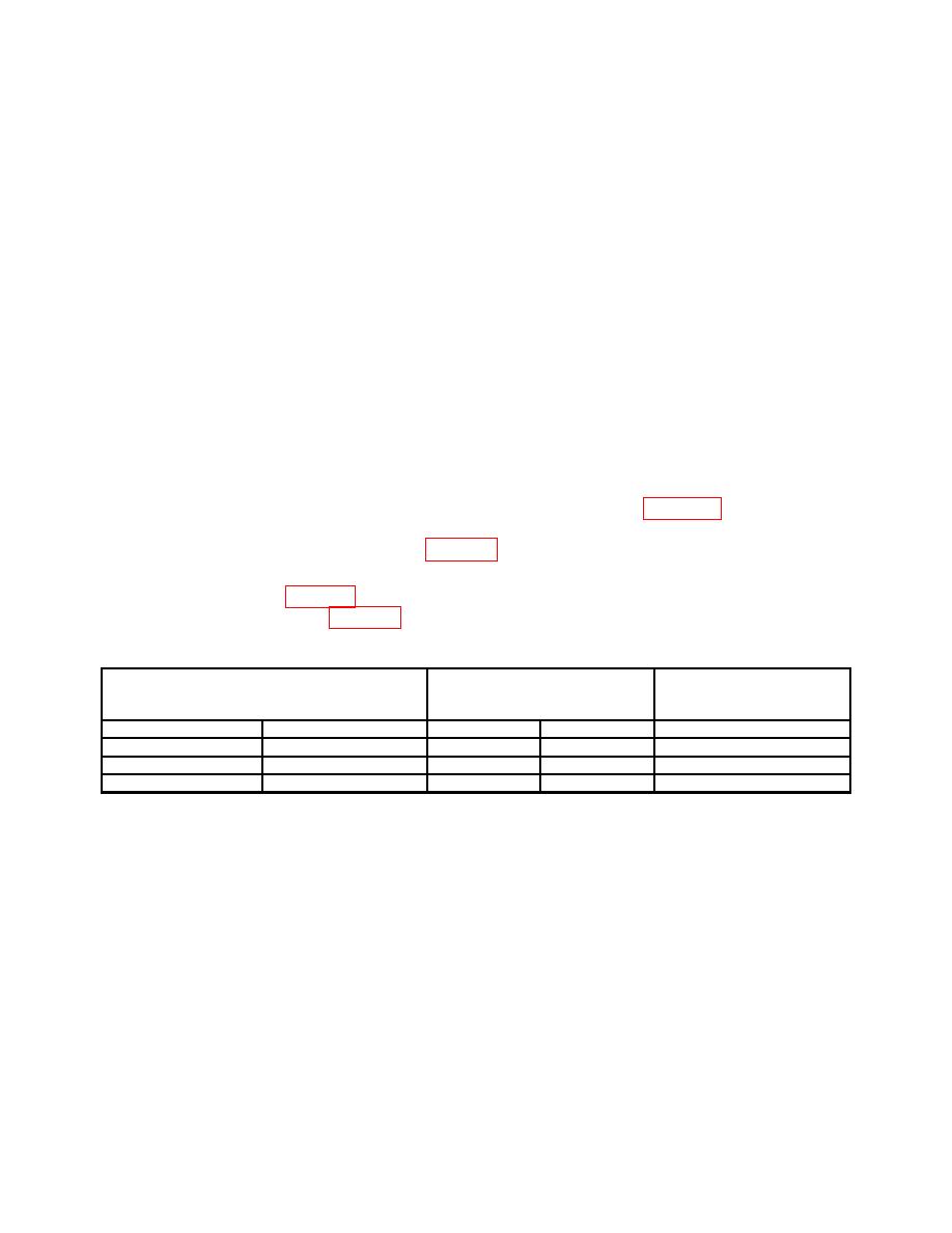
Test instrument
Test instrument
A TRIGGER LEVEL
Test instrument
stable display test
adjustments
MODE
SLOPE
YES
NO
b
NORM
IN:
b
P-P AUTO
IN:
b
P-P AUTO
OUT:
b
(7) Set HORIZONTAL MODE switch to B. Adjust B INTENSITY control for
suitable viewing.
(8) Verify a stable display can be obtained by adjusting B TRIGGER LEVEL
control in a position other than B RUNS AFTER DLY; if not, perform b below.
(9) Press B TRIGGER SLOPE pushbutton to IN and verify a stable display can be
obtained by adjusting B TRIGGER LEVEL control in a position other than B RUNS
AFTER DLY; if not, perform b below.
(10)Position controls as listed in (a) through (e) below:
(a) VERTICAL MODE CH 1 BOTH CH 2 switch to CH 2.
(b) VERTICAL MODE TRIGGER SOURCE CH 1 pushbutton to out position
(AN/USM-488).
25

