
TB 9-6625-2258-24
(10) Connect measuring receiver power sensor to RF OUTPUT 50 .
NOTE
Wait for 1 minute before proceeding to (11) below.
(11) Configure measuring receiver to measure frequency.
(12) If measuring receiver indication is not between 990 and 1010 MHz, perform
b below.
(13) Press TI FREQUENCY RANGE CW F2 key and set F2 M6 display to 1.900
GHz by pressing 1.9 with DATA ENTRY keys and then by pressing GHz/dBm/SEC
DATA ENTRY key.
NOTE
Wait for 1 minute before proceeding to (14) below.
(14) If measuring receiver frequency indication is not between 1890 and 1910 MHz,
perform b below.
(15) Press TI FREQUENCY RANGE key and press F1 M3 display to values as
listed in table 3.
(16) If measuring receiver frequency indications are not within the limits specified in
table 3, perform b below.
(17) Repeat (15) and (16) above for remaining TI FREQUENCY RANGE CW F1 or
F1 M3 display indications listed in table 3.
.
(18) Disconnect measuring receiver power sensor from RF OUTPUT 5
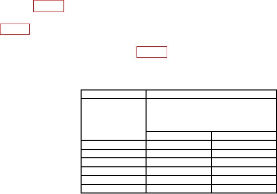
Table 3. CW F1 Frequency Check
Test instrument
Measuring receiver
FREQUENCY
Frequency
RANGE CW F1
indications
or F1 M3 display
(MHz)
indications
(GHz)
Min
Max
1
2.100
2090
2110
7.9001
7890
7910
8.1001
8090
8110
1
12.300
12,290
12,310
12.5001
12,490
12,510
1
17.900
17,890
17,910
1Press
FREQUENCY RANGE CW F1 key and enter desired frequency
with DATA ENTRY keys and then press GHz/dBm/SEC DATA ENTRY key.
(19) Press TI FREQUENCY RANGE CW F1 key and set F1 M3 display to 18.100
GHz by pressing 18.1 with DATA ENTRY keys and then by pressing GHz/dBm/SEC
DATA ENTRY key.
(20) Press TI FREQUENCY RANGE CW F2 key and set F2 M6 display to 27.400
GHz by pressing 27.4 with DATA ENTRY keys and then by pressing GHz/dBm/SEC
DATA ENTRY key.
6

