
TB 9-6625-2296-35
(2) Connect measuring receiver sensor module to TI T/R. Connect measuring
receiver MODULATION OUTPUT/AUDIO INPUT to audio analyzer INPUT HIGH.
(3) Set measuring receiver to measure FM, low pass filter 15 kHz, high pass filter
50 Hz, and PEAK/2 detector selected.
(4) Press key sequence listed in (a) through (h) below:
RF Gen Display
(a)
MODE RF GEN ................................................
Gen Menu
(b)
SETUP ...............................................................
RF Gen Setup
(c)
DATA ENTRY 5 ................................................
RF Gen Freq
(d)
DATA ENTRY 1 ................................................
750 kHz
(e)
DATA ENTRY 7 5 0 K......................................
RF Gen Level
(f)
DATA ENTRY 2 ................................................
0 dBm
(g)
DATA ENTRY 0 ENTER .................................
Return
(h)
Ret (F5) ..............................................................
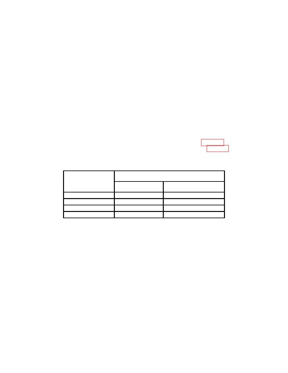
(5) Record measuring receiver indication as residual FM in table 18. Repeat this
step for remaining measuring receiver low pass filter settings listed in table 18 for TI RF
frequency 750 kHz.
Measuring receiver
TI
Low pass filter
Residual FM
RF frequency
settings
indications
750 kHz
15
kHz
750 kHz
3
kHz
900 MHz
3
kHz
900 MHz
>20
kHz
(6) Repeat (4) (e) and (5) above for MODE RF GEN frequency of 900 MHz.
(7) Press (F4) SOURCE (Modulation Source) key. Press DATA SCROLL arrow
keys until SOURCE 1 MOD FM is displayed and press DATA ENTRY ENTER key.
NOTE
Pressing More (F6) will scroll various options on the bottom of
the display. The options will change the functions assigned to
the F1 through F6 function keys. This may be necessary to
obtain the Freq (F2), Mod (F5), and A Freq (F1) options
required in the following tests.
(8) Set measuring receiver to select PEAK/2 detector, low pass filter to 3 kHz and
high pass filter to 300 Hz. Set audio analyzer to measure distortion in percent.
(9) Press Freq (F2) (RF Frequency Mode) and press DATA ENTRY keys to set
frequency to 750 kHz.
52

