
TB 9-6625-2311-24
(5) Connect ac divider input to calibrator OUTPUT V OHM A HI and
LO terminals.
(6) Connect RF PROBE to the ac divider output.
(7) Press MODE mV pushbutton.
(8) Adjust calibrator controls for 1 V at 10 kHz. If TI does not indicate
between 0.957 and 1.043 mV, perform b (1) through (8) below.
(9) Adjust calibrator controls for 3 V at 10 kHz. If TI does not indicate
between 2.908 and 3.092 mV, perform b (9) through (16) below.
(10) Adjust calibrator controls for 10 V at 10 kHz. If TI does not indicate
between 9.79 and 10.21 mV, perform b (17) through (24) below.
(11) Set calibrator to standby.
(12) Disconnect TI probe and ac divider from calibrator.
(13) C o n n e c t T I p r o b e t o c a l i b r a t o r O U T P U T V O H M A H I a n d
L O terminals.
(14) Set calibrator to operate.
(15) Adjust calibrator controls for 30 mV at 10 kHz. If TI does not indicate
between 29.39 and 30.61 mV, perform b (25) through (32) below.
(16) Adjust calibrator controls for 100 mV at 1 MHz. If TI does not indicate
between 98.9 and 101.1 mV, perform b (33) through (40) below.
(17) Adjust calibrator controls for 300 mV at 1 MHz. TI will indicate between
296.9 and 303.1 mV.
(18) Adjust calibrator controls for 1000 mV at 1 MHz. If TI does not indicate
between 989 and 1011 mV, perform b (41) through (48) below.
(19) Adjust calibrator controls for 3000 mV at 1 MHz. If TI does not indicate
between 2969 and 3031 mV, perform b (49) through (56) below.
(20) Set calibrator to standby.
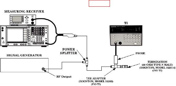
(21) Connect equipment as shown in figure 1.
Figure 1. Frequency response - equipment setup.
6

