
TB 9-6625-2316-35
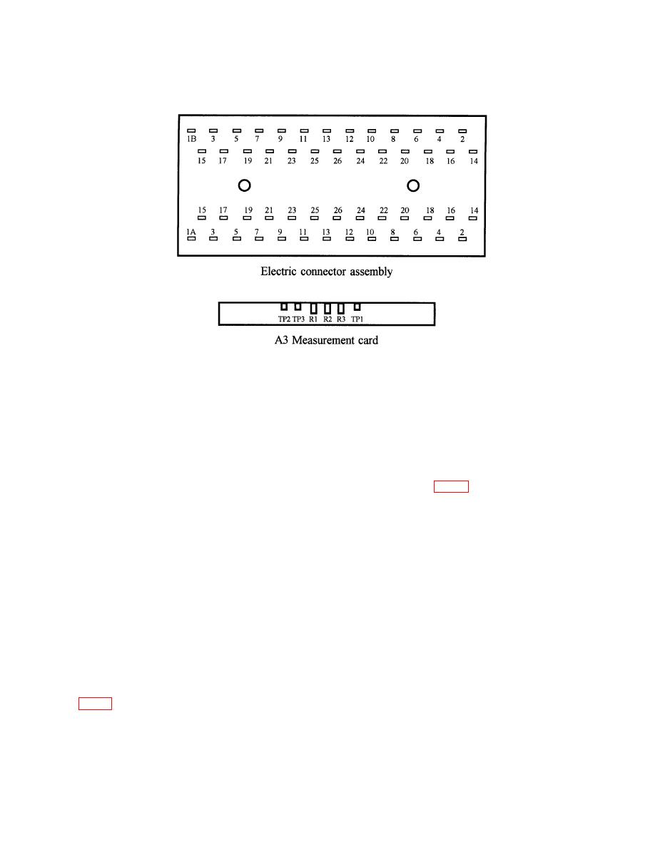
Figure 1. Test and connection points and adjustments.
b. Adjustments
(1) Set POWER switch to OFF and disconnect power cable from ac power source.
(2) Remove TI from its casing. Remove the end plate (located near the interface
connector J100). Ensure that potentiometers R1, R2, and R3 and the test points TP1, TP2,
and TP3, located on A3 measurement card, are readily accessible (fig. 1).
(3) Reconnect TI to ac source and set POWER switch to A.C.
(4) Set the FUNCTION switch to CONT. P.
(5) Set the CABLE LENGTH switch to 250.
(6) Set AUTO/SINGLE switch to SINGLE.
(7) Press the RESET pushbutton.
(8) Press the ADVANCE pushbutton once; circuit 01 will be under test, FAULT
light should be on, and TEST light should be on.
(9) Set resistance standard No. 2 for 20.0Ω and connect between pins 1A and 1B
5

