
TB 9-6625-2342-24
g. Adjust LEVEL SINE wave frequency until peak-to-peak signal on TI CRT decreases
to 4.2 divisions. Adjust TRIGGER LEVEL control and HORIZONTAL A AND B
SEC/DIV controls as necessary to obtain a stable display. LEVEL SINE frequency will be
150 MHz or greater.
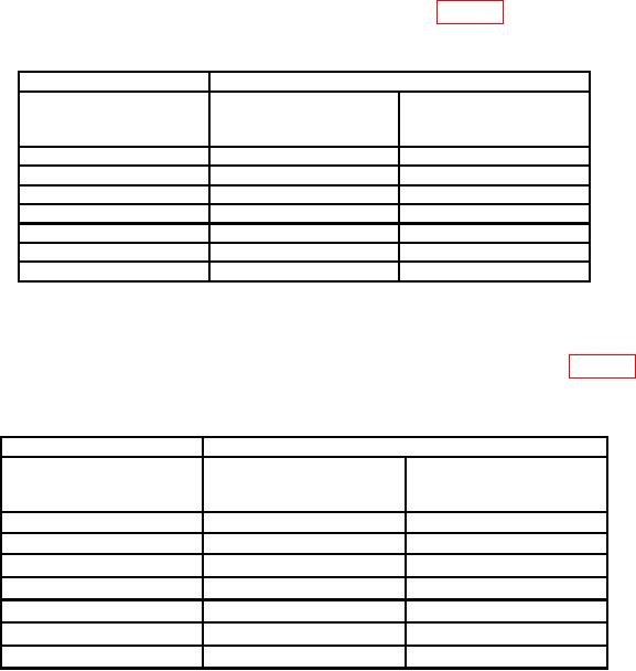
h. Repeat technique of f and g above for settings listed in table 5 below. LEVEL SINE
frequency will be within tolerance listed.
Table 5. Channel 1 Vertical Bandwidth Accuracy
Test instrument
Oscilloscope calibrator
LEVEL SINE
CH1 VOLTS/DIV
LEVEL SINE
frequency tolerance
settings
amplitude settings
( )
5 mV
30
mV
150 MHz
10 mV
60
mV
150 MHz
20 mV
120
mV
150 MHz
50 mV
300
mV
150 MHz
100 mV
600
mV
150 MHz
200 mV
1.2
V
150 MHz
500 mV
3
V
150 MHz
i. Set oscilloscope calibrator to standby. Select VERTICAL MODE, set CH 1 to off
and set CH 2 to on. Select oscilloscope calibrator CHAN 2 out.
j. Repeat technique of e through g above for CH 2 with settings listed in table 6 below.
Leveled sine wave frequency will be within tolerance listed.
Table 6. Channel 2 Vertical Bandwidth Accuracy
Test instrument
Oscilloscope calibrator
LEVEL SINE
CH2 VOLTS/DIV
frequency tolerance
LEVEL SINE
( )
settings
amplitude settings
5
mV
30 mV
150 MHz
10
mV
60 mV
150 MHz
20
mV
120 mV
150 MHz
50
mV
300
mV
150 MHz
100
mV
600
mV
150 MHz
200
mV
1.2
V
150 MHz
500
mV
3
V
150 MHz
k. Set oscilloscope calibrator to standby and disconnect equipment setup.
11. Internal and External Trigger Sensitivity Accuracy
NOTE
If TI does not perform as specified, perform adjustments as
indicated in SECTION IV.
a. Press PRGM button then press RECALL button in main menu.
b. Use arrow labeled switches to underline FPNL.

